
Zip Cpu
New Instruction Set
The Zip CPU Instruction set has been entirely redesigned and rebuilt. As a result, OpCodes are now five bits, instead of four, and there are several new instructions. The instruction set also offers compact instructions, sometimes (perhaps erroneously) called VLIW instructions, that stuff two instructions into one word. (They aren't true VLIW instructions, since each sub-instruction still requires its own clock cycle to execute.) This new instruction set was designed to be compatible at the assembly language level, simpler to decode, and to offer a space for divide and floating point instructions. The cost of this new instruction set is a loss of 1-2 bits of capability in the immediate offset range of each instruction. New instructions include six floating point instructions (for when I have a floating point unit), two divide instructions (signed and unsigned), a population count (counts the number of 1's bits), a bit reversal instruction, and a unique bus lock instruction that can be used to create an atomic test and set capability to support multiprocessor settings.
As an overview, the Zip CPU supports a set of two operand instructions, where the first operand (always a register) is the result. The only exception is the store instruction, where the first operand (always a register) is the source of the data to be stored. The second operand may either be a register, or a register plus an immediate.
Second, the Zip CPU supports two operating modes: a supervisor mode where interrupts are disabled, and a user mode where they are enabled. The CPU switches modes upon any interrupt (there are no interrupt vectors), and can also switch modes upon request from either user or supervisor.
Now for the details.
A Simplified Bus
The Wishbone Bus that the Zip CPU attaches to has been simplified: it is a 32-bit bus only. All transactions are 32-bits. All addresses reference 32-bit words. The number of address bits is configurable up to a 32-bit address space that will address 16GB of memory in this fashion. Since it is configurable, you can also reduce the address space as necessary to save space in the FPGA fabric. Since all operations are on full words, the bus is inherently neither big nor little endian. Finally, and because of this, all instructions (or instruction pairs) must fit within a single 32-bit access.
Register Set
The Zip CPU supports two sets of sixteen 32-bit registers, a supervisor and a user set.
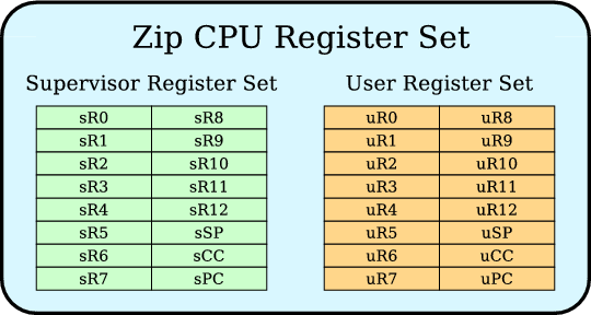
The supervisor set is used in interrupt mode, whereas the user set is used otherwise. Of this register set, the Program Counter (PC) is register 15, whereas the status register (SR) or condition code register (CC) is register 14. By convention, the stack pointer will be register 13 and noted as (SP)--although the instruction set allows it to be anything. The CPU can access both register sets via move instructions from the supervisor state, whereas the user state can only access the user registers.
The status register is special, and bears further mention. The lower 13 bits of the status register form a set of condition codes. Writes to other bits are preserved.
Of the condition codes, the bottom four bits are the current flags: Zero (Z), Carry (C), Negative (N), and Overflow (V). For those instructions that set flags, these flags will be set based upon the result of the instruction.
The next bit is a sleep bit. Writing a 1 to this bit will put the CPU to sleep. Setting this bit will cause the CPU to wait for an interrupt (if interrupts are enabled), or to completely halt (if interrupts are disabled). (Only the supervisor can halt the CPU, even though the user can put the CPU to sleep or switch to supervisor mode).
The sixth bit is a global interrupt enable bit (GIE). When this sixth bit is a '1' interrupts will be enabled, else disabled. When interrupts are disabled, the CPU will be in supervisor mode, otherwise it is in user mode. Thus, to execute a context switch, one only need enable or disable interrupts. (When an interrupt line goes high, interrupts will automatically be disabled, as the CPU switches to supervisor mode.)
The seventh bit is a step bit. This bit can be set from supervisor mode only. After setting this bit, should the supervisor mode process switch to user mode, it would then accomplish one instruction in user mode before returning to supervisor mode. (Two instructions, if they are packed.) Then, upon return to supervisor mode, this bit will be automatically cleared. This bit has no effect on the CPU while in supervisor mode.
This functionality was added to enable a userspace debugger functionality on a user process, working through supervisor mode of course.
The eighth bit is both a break enable bit (sCC) and a break status bit (uCC). The break enable bit controls whether a break instruction will halt the processor for an external debugger when in user mode (break enabled), or whether the break instruction will simply send send the CPU into supervisory mode. In the latter case, the break status bit in the uCC register will be set if a break is encountered during user mode processing. The break enable bit can only be set/changed in supervisor mode, whereas the break status bit can be cleared in supervisor mode, or it is otherwise cleared upon any return to user mode.
This functionality was added to enable a debugger, both external and internal, to set and manage breakpoints.
The next several bits are exception bits. They are set when/if that particular exception takes place. If it takes place in user mode, the exception bit is set in uCC and the CPU switches to supervisor mode. If the exception takes place in supervisor mode, the bit is set in sCC and the CPU halts for a debugger. The user mode exception can either be cleared by the supervisor writing to the uCC register, or upon any return to user mode instruction. The supervisor exception bits can be cleared by either an external debugger, or by a system reset. These exception bits are:
- 9. Illegal instruction, referring to either an unimplemented opcode, or from an address which received a bus error.
- 10. Bus Error, indicating that the CPU tried to use the bus to access an illegal address.
- 11. Divide by zero
- 12. Floating point (once the FPU is built)
Bit 13 is a VLIW phase bit. Should an exception (not an interrupt) occurr when trying to execute the first half of a VLIW instruction, this bit bill be set when the CPU enters supervisor mode. It is cleared upon any return to user mode, and upon any system reset.
Bit 14 is a write only clear-instruction cache bit. Setting this bit to one will clear the instruction cache, and reset the bit back to zero (hence write only). Currently, it only works from supervisor mode.
The status register bits are shown below:
| 14 | 13 | 12 | 11 | 10 | 9 | 8 | 7 | 6 | 5 | 4 | 3 | 2 | 1 | 0 |
|---|---|---|---|---|---|---|---|---|---|---|---|---|---|---|
| ClrICache | VLIW-Ph | FPE | DIVE | BUSERR | TRAP | ILL | BREAKEN | STEP | GIE | SLEEP | V | N | C | Z |
Native Instructions
The Zip CPU instruction set has one of two basic formats, with a small number of exceptions. These formats are shown below:
| Op Code | 31..24 | 23..16 | 15..8 | 7..0 | ||||||||||||||||||||||||||||
|---|---|---|---|---|---|---|---|---|---|---|---|---|---|---|---|---|---|---|---|---|---|---|---|---|---|---|---|---|---|---|---|---|
| Standard | 0 | DR | OpCode | CND | 0 | 18-bit signed immediate | ||||||||||||||||||||||||||
| 1 | BR | 14-bit signed immediate | ||||||||||||||||||||||||||||||
| MOV | 5'hf | A | BR | B | 13-bit signed immediate | |||||||||||||||||||||||||||
| LDI | 4'hb | 23-bit signed immediate | ||||||||||||||||||||||||||||||
| VLIW | 1 | DR | OpCode | VCND | 0 | Imm | ||||||||||||||||||||||||||
| 1 | BR | |||||||||||||||||||||||||||||||
| 4'hb | Imm | |||||||||||||||||||||||||||||||
| DR | OpCode | 0 | Imm | |||||||||||||||||||||||||||||
| 1 | BR | |||||||||||||||||||||||||||||||
| 4'hb | Imm | |||||||||||||||||||||||||||||||
In this format, the Standard line is the basic format for all 32--bit instructions. The two exceptions are the move instruction, which needs space to encode whether registers are user or supervisor registers (marked here as the A and B bits), and the load immediate instruction which has been stripped down so that as many bits as possible may be used to describe the immediate value.
The instruction set now optionally supports a compact format as well. This is the VLIW format. Using this format, two instructions may be encoded in a single instruction word, with the instruction encoded in the higher order bits being the "first" instruction. The three bit condition is then modified such that the first bit specifies whether or not the condition is to be applied to the second instruction, and the second two bits specify the low order two bits of the condition. Hence a 3'h1 would specify that the first instruction is to be executed on a less than condition, whereas the second instruction will always be executed. Likewise a 3'h7 condition would mean that both first and second instructions will be executed if the zero flag is not set. Other than the loss of any potential immediate address space, these instructions are identical to the first set.
The instruction set now has the space for 32-opcodes. These are defined as follows:
| OpCode | Instruction | Sets CC | |
|---|---|---|---|
| 5'h00 | SUB | Subtract operand B from DR, result into DR | Y |
| 5'h01 | AND | Bitwise AND | |
| 5'h02 | ADD | Add two numbers | |
| 5'h03 | OR | Bitwise OR | |
| 5'h04 | XOR | Exclusive OR | |
| 5'h05 | LSR | Logical shift DR right by OpB bits | |
| 5'h06 | LSL | Logical shift DR left by OpB bits | |
| 5'h07 | ASR | Arithmetic shift right | |
| 5'h08 | MPY | A 32x32 bit multiply into 32 bits | |
| 5'h09 | LDILO | Load into lower 16 bits | N |
| 5'h0a | MPYUHI | Upper 32 bits of a 32x32->64 bit unsigned multiply | Y |
| 5'h0b | MPYSHI | Upper 32 bits of a 32x32->64 bit signed multiply | |
| 5'h0c | BREV | Bit reverse OpB into DR | N |
| 5'h0d | POPC | Population Count of OpB into DR | Y |
| 5'h0e | ROL | Rotate left DR by OpB bits | |
| 5'h0f | MOV | Move register | N |
| 5'h10 | CMP | Compare (SUB, w/o setting result) | Y |
| 5'h11 | TST | Test (AND w/o setting result) | |
| 5'h12 | LOD | Load DR from memory address in OpB | N |
| 5'h13 | STO | Store DR into memory at address OpB | |
| 5'h14 | DIVU | Divide, unsigned, DR by OpB | Y |
| 5'h15 | DIVS | Divide, signed | |
| 5'h16/7 | LDI | Load Immediate into DR | N |
| 5'h18 | FPADD | Floating point add | Y |
| NOOP | No operation (Destination Reg=PC) | N | |
| 5'h19 | FPSUB | Floating point subtract | Y |
| BREAK | Break point for debugger support (DR=PC) | N | |
| 5'h1a | FPMPY | Floating point multiply | Y |
| LOCK | Lock bus for atomic access (DR=PC) | N | |
| 5'h1b | FPDIV | Floating point divide | Y |
| 5'h1c | FPCVT | Convert integer to floating point | Y |
| 5'h1d | FPINT | Convert floating point to integer | |
| 5'h1e | Reserved for future use | ||
| 5'h1f | |||
Notice the three instruction: NOOP, BREAK, and LOCK. These have opcodes of 5'h18, 5'h19, and 5'h1a respectively. They are carved out of the floating point units opcodes, and differentiated by the fact that their resulting register is either the CC or PC register. (It never made sense to do a floating point instruction into the CC or PC register anyway ...) The BREAK instruction is designed to trap the CPU without ever entering into the ALU. It is useful for debugging purposes. The immediate field of the BREAK instruction is available for the debugger to store information within. The LOCK instruction waits for the decode and prefetch pipeline stages to fill with instructions before locking the bus and letting the following string of memory operations complete. It was initially designed to support a test and set operation, although it has since been modified to permit a single ALU operation in between two memory operations. Hence one could do a "LOCK, LOD (R0),R1, ADD 1,R1, STO R1,(R0)" to implement an atomic increment. (Actually, since the Zip CPU doesn't truly support a LOCK bit on the wishbone bus, what really happens is that the CYC line is kept high throughout the operation. This line may be tied to a LOCK line if you would like to use the Zip CPU with a bus that supports LOCKing.)
Conditional Instructions
Most, although not quite all, instructions are conditional. From the four condition code flags, eight conditions are defined. These are:
| Code | Mneumonic | Condition |
|---|---|---|
| 3'h0 | (None) | Always |
| 3'h1 | .LT | Less than (N set) |
| 3'h2 | .Z | Equal (Zero set) |
| 3'h3 | .NZ | Not equal to (!Z) |
| 3'h4 | .GT | Greater than (N not set, Z not set) |
| 3'h5 | .GE | Greater than or equal (N not set, Z irrelevant) |
| 3'h6 | .C | Carry set |
| 3'h7 | .V | Overflow set |
Conditions in the Zip CPU instruction set may also be stacked: any compare or test instruction that executes will always set the flags, regardless of the previous flag condition. No other conditionally executed instructions will set the flags. This allows for the creation of a multicycle compare instruction, as in
-
CMP '$',R0
CMP.Z 'G',R1
CMP.Z 'P',R2
BNZ failedmatch
Operand B
Many instruction forms have a 19-bit source "Operand B" associated with them. This Operand B is either equal to a register plus a signed immediate offset, or an immediate offset by itself. This value is encoded as,
| 18 | 17 | 16 | 15 | 14 | 13 | 12 | 11 | 10 | 9 | 8 | 7 | 6 | 5 | 4 | 3 | 2 | 1 | 0 |
|---|---|---|---|---|---|---|---|---|---|---|---|---|---|---|---|---|---|---|
| 1'b0 | Signed Immediate Value | |||||||||||||||||
| 1'b1 | Register | Signed immediate offset | ||||||||||||||||
The move operation is a special exception to this pattern, necessitated by the fact that the CPU needs access to non--supervisory registers while in supervisory mode. Therefore, the MOV instruction offers access to these registers when in supervisory mode. To keep the compiler simple, the extra bits are ignored in non-supervisory mode (as though they didn't exist), rather than being mapped to new instructions or additional capabilities. The bits indicating which register set each register lies within are the A-map and B-map bits. Further, because a load immediate instruction exists, there is no move capability between an immediate and a register: all moves come from either a register or a register plus an offset.
This actually leads to a bit of a problem: since the MOV instruction encodes which register set each register is coming from or moving to, how shall a compiler or assembler know how to compile a MOV instruction without knowing the mode of the CPU at the time? For this reason, the compiler will assume all MOV registers are supervisor registers, and display them as normal registers. Anything with the user bit set will be treated as a user register. The CPU will quietly ignore the supervisor bits while in user mode, and anything marked as a user register will always be valid.
Addressing Mode(s)
The ZIP CPU supports two addressing modes: register plus immediate, and immediate address. Addresses are therefore encoded in the same fashion as
Operand B's, shown above.
The Zip CPU has no support for indexed addressing whereby the sum of two registers creates a memory address, nor does it have any support for
pre/post increment or decrement addressing modes.
Move Operands
The previous set of operands would be perfect and complete, save only that the CPU needs access to non--supervisory registers while in supervisory mode. Therefore, the MOV instruction is special and offers access to these registers ... when in supervisory mode. To keep the compiler simple, the extra bits are ignored in non-supervisory mode (as though they didn't exist), rather than being mapped to new instructions or additional capabilities. The bits indicating which register set each register lies within are the A-Usr and B-Usr bits. Further, because a load immediate instruction exists, there is no move capability between an immediate and a register: all moves come from either a register or a register plus an offset.
This actually leads to a bit of a problem: since the MOV instruction encodes which register set each register is coming from or moving to, how shall a compiler or assembler know how to compile a MOV instruction without knowing the mode of the CPU at the time? For this reason, the compiler will assume all MOV registers are from the current register set, encoded as the supervisor register set, yet displayed normally. Anything with the user bit set will be treated as a user register. The CPU will then quietly ignore the supervisor bits while in user mode, and anything marked as a user register will always be valid.
Floating Point
The ZIP CPU does not support floating point operations. However, the instruction set reserves several opcodes for a future floating point capability, together with a bit in the condition codes to capture any floating point exceptions.
operations.When implemented, the Zip CPU would support 32--bit single precision floats only.
The current architecture does support an illegal instruction interrupt. Any attempt to execute a floating point instruction will trigger this interrupt. Soft floating point emulation could then take place.
Compared with RISC-V
The lowRISC project has chosen the RISC-V architecture, and posted their reasons for doing so. When comparing the ZIP Instruction Set architecture to the RISC-V ISA, you can see the following comparison using the criteria they define here:
| Feature | Zip CPU | RISC-V |
|---|---|---|
| Base + Extensions | Yes, the Zip ISA has room for extensions | Yes |
| Compact Code | Yes, with VLIW two instructions can fit in 32-bits. | Yes |
| 32-bit Floating Point Support | None (yet--work in progress) | Yes |
| 64-bit or 128-bit Floating Point | No, all data are 32-bits only | Yes |
| 32-bit Address | Yes | Yes |
| 64-bit Address | No | Yes |
| 128-bit Address | No | Yes |
| GCC Support | Yes | Yes |
| Linux | Not yet--missing the MMU | Yes |
A fascinating observation regarding RISC-V, however, is that much of their instruction set space remains to be defined. Like other "full featured" processors, (OpenRISC has 200+ instructions defined) their instruction space has not been completely fleshed out. ZipCPU instructions, on the other hand, are simple enough that (other than the FPU) there are no giant holes in the ZipCPU instruction space.
Derived Instructions
| Mapped | Actual | Notes |
|---|---|---|
| ABS Rx | TST -1,Rx NEG.LT Rx | Absolute value, depends upon the derived NEG instruction below. |
| ADD Ra,Rx ADDC Rb,Ry | ADD Ra,Rx ADD.C $1,Ry ADD Rb,Ry | Add with carry |
| BRA.cond +/-$Addr | MOV.cond $Addr+PC,PC | Branch/jump on condition. Works for 14 bit address offsets. |
| ADD.cond $Addr,PC | Branch/jump on condition that works for 18-bit offsets. It does not set flags, and it does support early branching. | |
| LDI $Addr,Rx ADD.cond Rx,PC | Branch/jump on condition. Works for 23 bit address offsets, but costs a register and an extra one (or two) instruction(s). Also supported by early branching. | |
| BNC PC+$Addr |
TEST $Carry,CC MOV.Z PC+$addr,PC |
Example of a branch on an unsupported condition, in this case a branch on not carry |
| CLRF.NZ Rx | XOR.NZ Rx,Rx | Clear Rx, and flags, if the Z-bit is not set |
| CLR Rx | LDI $0,Rx | Clears Rx, leaves flags untouched. This instruction cannot be conditional. |
| EXCH.W Rx | ROL $16,Rx | Exchanges the top and bottom 16'bit words of Rx |
| HALT | Or $SLEEP,CC | Executed while in supervisor mode. In user mode this is simply a wait until interrupt instruction. |
| INT | LDI $0,CC | Switches from user to supervisor mode. |
| IRET | OR $GIE,CC | Also an RTU instruction (Return to Userspace) |
| JMP R6+$Addr | MOV $Addr(R6),PC | |
| JSR PC+$Addr | MOV $1+PC,R0 ADD $Addr-PC,PC |
Jump to subroutine. Note that this high speed version of a JSR call needs a register to hold the last PC address. In its favor, it doesn't suffer the mandatory memory access of the more traditional approach. |
| LDI.l $val,Rx |
BREV bit-reversed-HIBITS($val),Rx LDILO LOBITS($val),Rx | Sadly, there's not enough instruction space to load a complete immediate value into any register. Therefore, fully loading any register takes two cycles. The LDIHI (load immediate high) and LDILO (load immediate low) instructions have been created to facilitate this. Further, the assembler will quietly turn any LDI #x,Rx instruction into this instruction if either #x doesn't fit within the 23--bit immediate operand field, or if the instruction is conditional, or if #x refers to a to-be-resolved symbol. |
| LOD.b $addr,Rx |
LDI $addr,Ra LDI $addr,Rb LSR $2,Ra AND $3,Rb LOD (Ra),Rx LSL $3,Rb SUB $32,Rb ROL Rb,Rx AND $0ffh,Rx | This CPU is designed for 32'bit word
length instructions. Byte addressing is not supported by the CPU or
the bus, so it therefore takes more work to do. Note that in this example, $Addr is a byte-wise address, where all other addresses are 32-bit wordlength addresses. For this reason, we needed to drop the bottom two bits. This also limits the address space of character accesses from 16GB down to 4GB. |
| LJMP $Addr | LOD (PC),PC $Addr | This instruction is followed by the 32-bit address to jump to. Jumps of this fashion are supported by the linker, and the early branch logic. |
| LJSR $Addr | MOV 2(PC),R0 LOD (PC),PC $Addr | This is a simple modification to the LJMP instruction. |
| LSL $1,Rx LSLC $1,Ry |
LSL $1,Ry LSL $1,Rx OR.C $1,Ry | Logical shift left with carry. Note that the instruction order is now backwards, to keep the conditions valid. That is, LSL sets the carry flag, so if we did this the othe way with Rx before Ry, then the condition flag wouldn't have been right for an OR correction at the end. |
| LSR $1,Rx LSRC $1,Ry |
CLR Rz LSR $1,Ry BREV.C $1,Rz LSR $1,Rx OR Rz,Rx | Logical shift right with carry |
| NEG.C Rx | SUB.C $1,Rx XOR.C $-1,Rx | Negate, may be conditional |
| NOOP | NOOP | While there are many operations that do nothing, such as MOV Rx,Rx, or OR $0,Rx, these operations have consequences in that they might stall the bus if Rx isn't ready yet. For this reason, we have a dedicated NOOP instruction. |
| NOT Rx | XOR $-1,Rx | |
| POP Rx | LOD (SP),Rx ADD $1,SP |
Note that for pipelining purposes, it helps to coalesce all the ADD (SUB) operations into one after (before) a group of LOD (STO) instructions, and then to do the operations in sequential order. This will also guarantee a pipelined memory operation. |
| PUSH Rx |
SUB 1,SP STO Rx,(SP) | |
| RESET | LDI 1,R0 STO R0,$watchdog(R12) NOOP NOOP |
This depends upon the peripheral base address already being in R12.
Another opportunity might be to jump to the reset address from within supervisor mode. |
| RET | MOV R0,PC | Recall that the JSR command left the address to return to in the register set. Were that register R12, this returns us back to where we came from. Unlike the traditional RETN structure of some other architectures, this instruction doesn't suffer a stall on memory read from the stack. |
| RTU | OR $GIE,CC | Also known as a Return-To-USER space command, sometimes known as IRET (interrupt return) in other architectures. |
| STEP Rr,Rt | LSR $1,Rr XOR.C Rt,Rr | Step a Galois implementation of a Linear Feedback Shift Register, Rr, using taps Rt |
| STO.b Rx,$addr |
LDI $addr,Ra LDI $addr,Rb LSR $2,Ra AND $3,Rb SUB $32,Rb LOD (Ra),Ry AND $0ffh,Rx AND $-0ffh,Ry ROL Rb,Rx OR Rx,Ry STO Ry,(Ra) | This CPU and it's bus are not optimized
for byte-wise operations. Note that in this example, $addr is a byte-wise address, whereas in all of our other examples it is a 32-bit word address. This also limits the address space of character accesses from 16 MB down to 4MB.F Further, this instruction implies a byte ordering, such as big or little endian. |
| SWAP Rx,Ry |
XOR Ry,Rx XOR Rx,Ry XOR Ry,Rx | While no extra registers are needed, this example does take 3-clocks. |
| TRAP #X | LDILO $x,R0 AND ~$GIE,CC | This approach uses R0 as a TRAP address. It works because anytime a user lowers the GIE flag a trap bit is also set within the CC register. Therefore, upon entering the supervisor state, the CPU only needs to check this bit to know that it got there via a TRAP. The trap could be made conditional by making the AND conditional. |
| TST Rx | TST $-1,Rx | Set the condition codes based upon Rx. Could also do a CMP $0,Rx. |
| WAIT | Or $GIE|$SLEEP,CC | Wait 'til interrupt. |