
UART to / from fiber optic
Project maintainers
Details
Created: Nov 13, 2013
Updated: Dec 24, 2013
SVN Updated: Nov 26, 2013
SVN: Browse
Latest version: download (might take a bit to start...)
Statistics: View
Bugs: 0 reported / 0 solved
Other project properties
Language:VHDL
Development status:Mature
Additional info:
WishBone compliant: Yes
WishBone version: n/a
License: LGPL
Introduction
Transmitter and receiver in FPGA for converting UART to/from audio fiber optics.
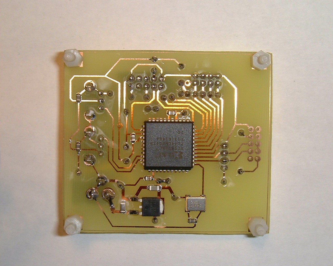
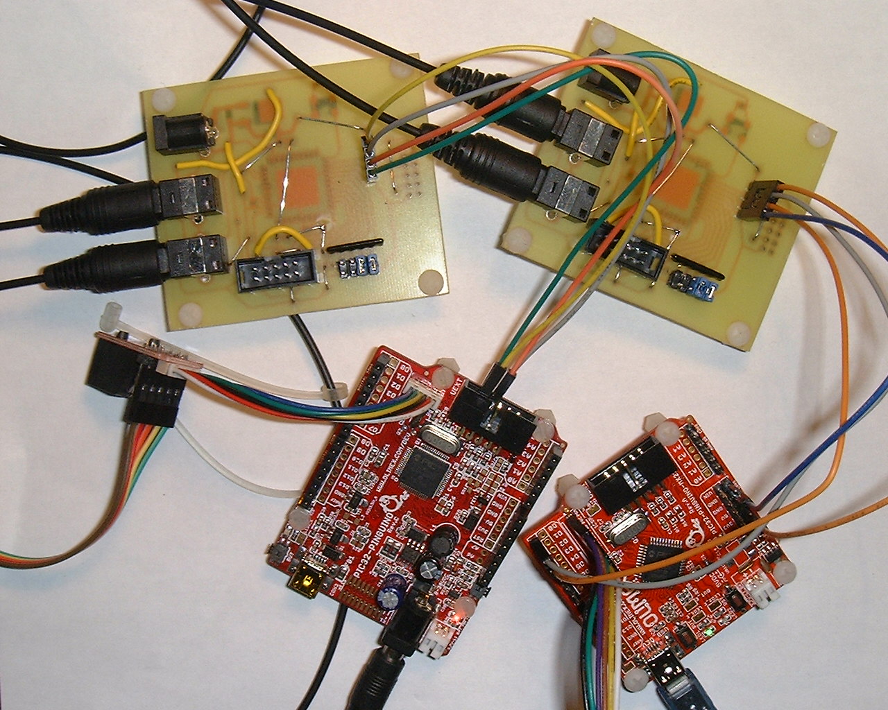
Photo of an assembled board with annotation
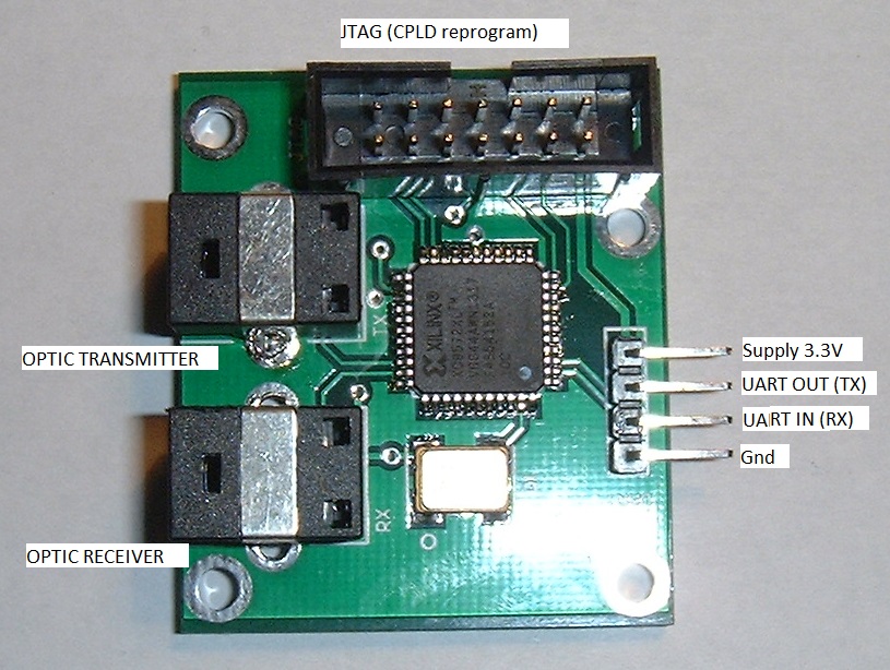
It is wishbone compliant because using an UART , it can be added to a Wishbone UART and be of interest for a Wishbone implementer. This core is well tested.
They is two versions:
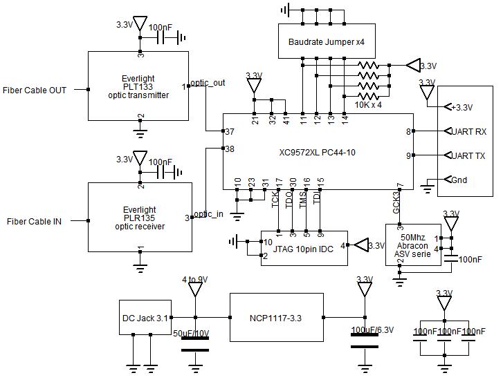
-Fixed baudrate (0 to 2.5Mbit/s) - a full set of 2 transmitter and 2 receiver fit in a single XC9572XL CPLD
-variable baudrate 50Mhz/n*p where n between 20 to 100 fiber optic baudrate and p>=1 baudrate divider. Fit 1x transmiter + receiver in a single XC9572XL CPLD. The baudrate is adjustable from external pins DIP SWITCH or jumper.
The fiber represent signal as follow :
0 : 1 period of low frequency F signal
1 : 2 periods of high frequency 2xF signal
why en encoder/decoder and why not connect directly the UART to a fiber optic transmiter and receiver :
Because it would not work. The optical receiver for audio fiber optic is designed for AC signal (0.1 to 16Mhz).
A duplex communication use 2 fiber optics .
the prototype use a XC9572XL CPLD from Xilinx
The test work with several MByte transmitted and received at 1.25Mbaud (packets of 64byte data checked by CRC).
the UART used are PIC32 procesors exchanging data on fiber optic (the UART is driven by DMA, requiring less effort for the CPU)
Prototype
The prototype use two Microchip processors communicating over fiber optic
PIC32MX220 and PIC32MX440
4x optical transceiver for audio :
Everlight PLR137 / PLT137
2 x fiber optic cables
1x CPLD board with Xilinx XC9572XL CPLD (which fit the two receiver and two transmitter).
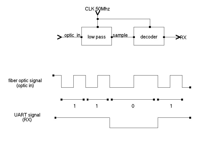
The receiver
The receiver sample the fiber optic signal and measure duration of periods of the input (optic_in)
The receiver output
-0 for long period of input signa
-1 for short period of input signal
The sampling frequency is 50Mhz (clock available in the CPLD)
The receiver integrate a low pass filter and the decoder itself that measure the frequency of the input signal (from the fiber).
the receiver then produce a signal suitable for the UART RX pin.
The low pass is probably not required but very easy to implement.
The receiver integrate also a "learn" bit that say if the peiods should be measured at low-to-high of high-to-low transitions on the input. This is an important phase information that the receiver automatically detect during reception.
The receiver synchronize itself with the received signal, that is a multiple of the UART bitrate.
Receiver VHDL code
--fixed bitrate version (1.25Mbit/s 8N1)
library IEEE;
use IEEE.STD_LOGIC_1164.ALL;
entity spdif_to_RX is
Port ( iCLK : in STD_LOGIC;
optic_in : in STD_LOGIC;
RX : out STD_LOGIC;
learn_out : out STD_LOGIC
);
end spdif_to_RX;
architecture Behavioral of spdif_to_RX is
--low pass
signal q1 : STD_LOGIC;
signal q2 : STD_LOGIC;
signal samp : STD_LOGIC;
--RX generator
signal samp2 : STD_LOGIC;
signal cnt : natural range 0 to 63;
signal learn : STD_LOGIC;
--constant periode_1_max : natural := (20+7);
--constant periode_0_min : natural := (40-7);
--signal RX1 : STD_LOGIC;
signal RX2 : STD_LOGIC;
begin
learn_out
input_low_pass:process (iCLK)
begin
if (iCLK'event and iCLK= '1') then
q1
q2
if(q1=q2)then
samp
end if;
end if;
end process;
fiber_decoder:process (iCLK)
begin
if (iCLK'event and iCLK= '1') then
samp2
if(samp2/=samp and samp=learn) then
if(cnt>33) then
RX
RX2
elsif (cnt
RX
RX2
elsif(cnt
RX2
else
learn
end if;
cnt
else
if(cnt=20) then
RX
end if;
if(cnt
cnt
end if;
end if;
end if;
end process;
end Behavioral;
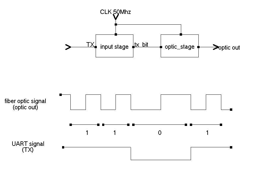
The transmiter
The transmitter receive UART signal TX and produce the fiber optic signal.
The transmitter core must synchronise the bits from TX with the local clock and at the same time synchronize itself with the START bits from the UART.
The transmittter first synchronize itself with the input START bits, then output a synchronized version (tx_bit).
The optic_stage process then transform tx_bit to optic_out, the signal suitable for the fiber optic.
The transmitter use the blank formed by the STOP bits to re-synchronize with the next START bit. When the input in uninterrupted data (ie each STOP bit is immediately followed by a START bit) and when bit_div is equal to 1 (ie the UART bitrate and fiber optic bitrate are equal) , then the transmitter relie only on the exact match of the local ocillator with the incoming data.
Any difference is corrected at the end of incoming packet data (STOP bit not followed by START bit).
when bit_div>1, re-synchronization occur at each byte and the incoming data can have a bit clock slightly different than the expected one.
As described, the transmitter core have many advantage.
Transmitter VHDL
--fixed bitrate version (1.25Mbit/s 8N1)
library IEEE;
use IEEE.STD_LOGIC_1164.ALL;
use IEEE.STD_LOGIC_ARITH.ALL;
use IEEE.std_logic_unsigned.all;
--use IEEE.NUMERIC_STD.ALL;
entity TX_to_spdif_full is
Port ( iCLK : in STD_LOGIC;
TX : in STD_LOGIC;
optic_out : out STD_LOGIC
);
end TX_to_spdif_full;
architecture Behavioral of TX_to_spdif_full is
--output flip-flop
signal optic_flop:STD_LOGIC:='0';
--optic stage
signal optic_cnt : STD_LOGIC_VECTOR(3 downto 0); --value 0 to 9 (divide 50Mhz/10=5Mhz)
signal half0 : STD_LOGIC;
signal half1 : STD_LOGIC;
signal optic_bit:STD_LOGIC;
--input stage
signal tx_cnt : STD_LOGIC_VECTOR(4 downto 0); --value 0-19 (divide 50Mhz/20=2.5Mhz)
signal tx_bit:STD_LOGIC:='1';
signal start_detected : STD_LOGIC:='0';
signal tx_half : STD_LOGIC; --1/2 bit
signal bit_position : STD_LOGIC_VECTOR(3 downto 0);--value 0-9 (bit position from start to stop)
begin
optic_out
--generate signal on fiber optic
optic_stage:process (iCLK)
begin
if (iCLK'event and iCLK = '1') then
if(optic_cnt=9) then --divide 50Mhz / 10 = 5 Mhz
half0
if(half0='1') then
half1
end if;
if(optic_bit='1' or half0='0') then
optic_flop
end if;
if((half0='1') and (half1='1'))then
optic_bit
-- optic_flop
end if;
optic_cnt'0');
else
optic_cnt
end if;
end if;
end process;
--Synchronize input (TX pin) with local clock
input_stage: process (iCLK,TX)
begin
if (iCLK'event and iCLK = '1') then
if(start_detected='0') then
if(TX='0') then
start_detected
tx_cnt'0');
bit_position'0');
tx_half
end if;
else --start detected=1
if(tx_cnt=19) then --0.5 bit time
if(tx_half='0')then
tx_bit
elsif(tx_half='1')then
if(bit_position/=9)then
bit_position
end if;
if(bit_position=9 and tx_bit='1') then --stop bit
bit_position'0');
if(TX='1')then
start_detected
end if;
end if;
end if;
tx_half
tx_cnt'0');
else
tx_cnt
end if;
end if;--start detected
end if;--clk event
end process;
end Behavioral;
Application
This is my application and it is also used for intensive testing.
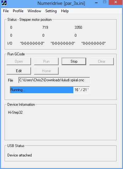
This is a machine (Robot) controller . The application communicate with USB-to-fiberoptic.
On the other side, the fiberoptic-to-machine receive the commands and provide ACK (aknowledge) . All communication are segmented as packets and CRC controlled .
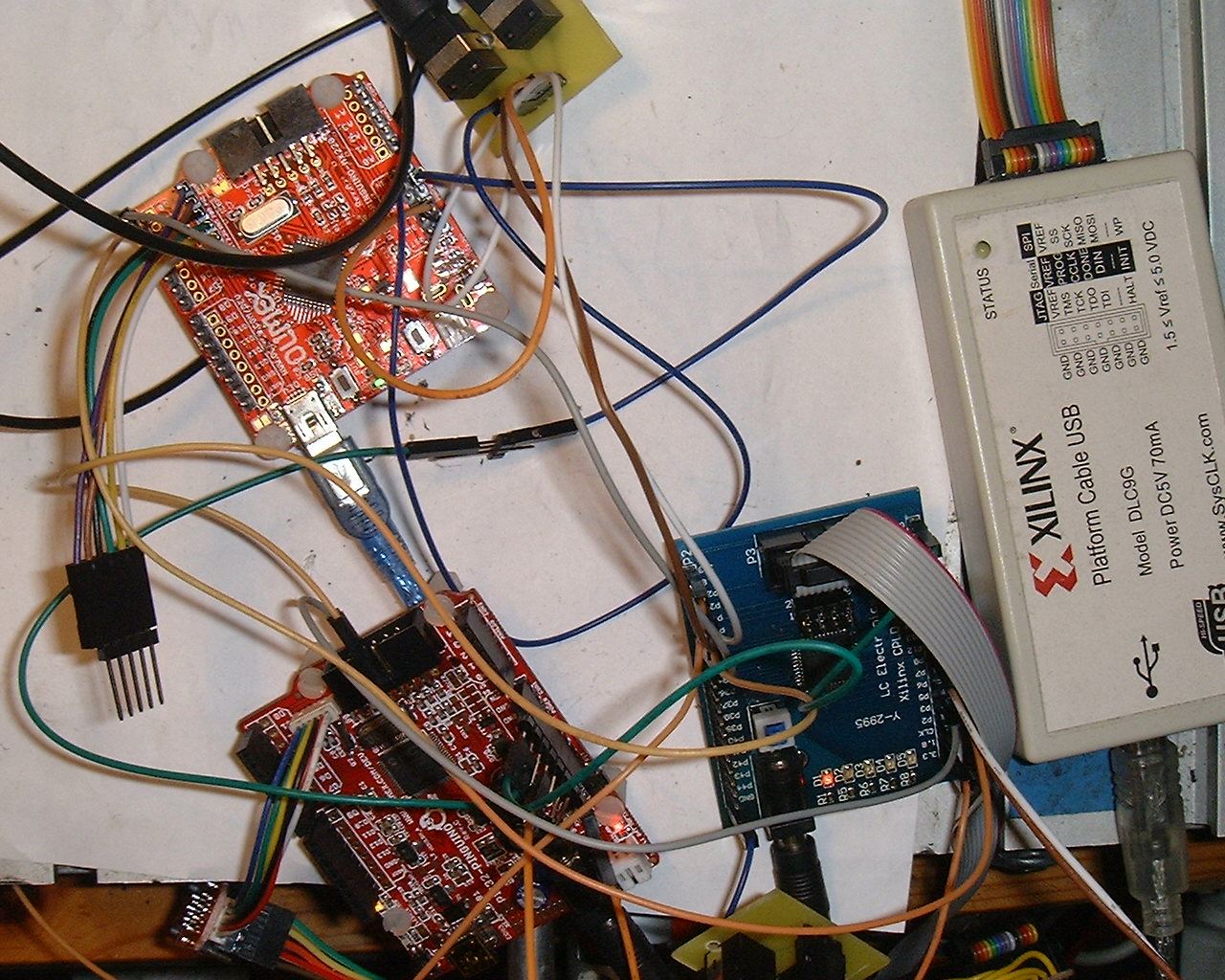
The image show a real testing (with two PIC32 cards , and the CPLD ).
The 3 number on the top are machine position
The 3 number on the bottom are total CRC error received by both parts (which is always 0 in normal use). The errors where numerous during developpement . It took 24hour to discover that my CPLD evaluation board did not have a 25Mhz clock as documented but a 50Mhz.
SPDIF audio fiber optics
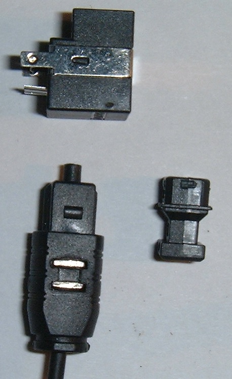
Audio SPDIF fiber optic (TOSLINK)
with Everlight PLR137 SPDIF transceiver.
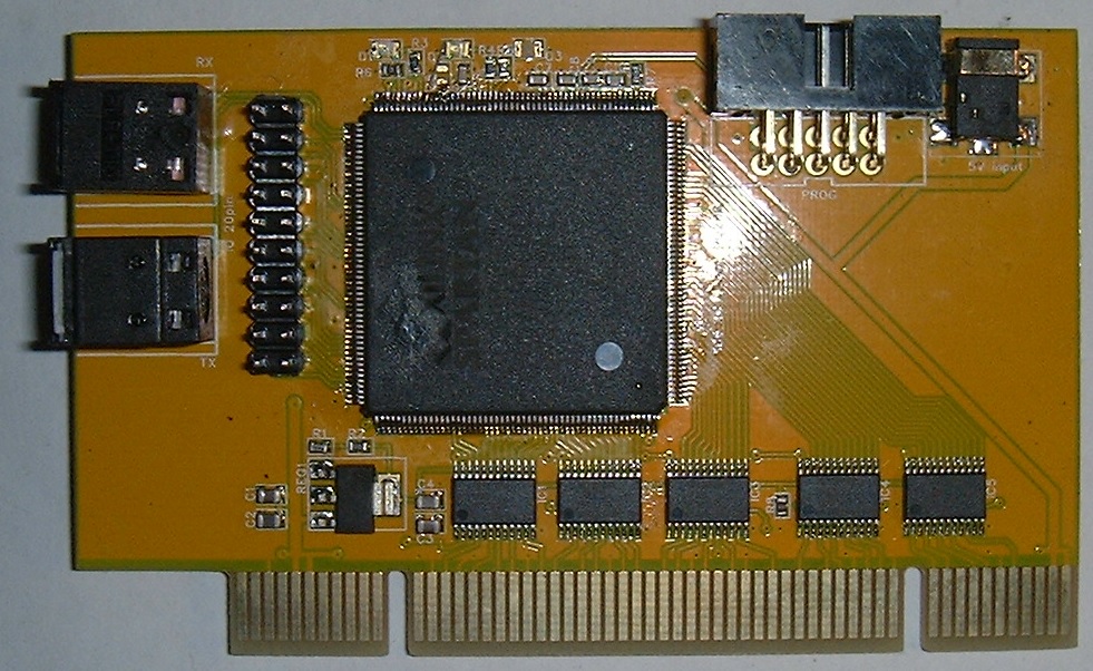
PCI to fiber
A PCI card with fiber optic transceiver.
Variable baudrate
The variable baudrate version use two values :
period STD_LOGIC_VECTOR (6 downto 0)
this is the number of 50Mhz clock period for each bit on the fiber optic.
It must be not too small otherwise the signal would be difficult to sample . a value not smaller than 20 (5Mhz high freq) to 100 (500Khz low freq) would be ok.
bit_div STD_LOGIC_VECTOR (6 downto 0)
this is the ratio between baudrate on the fiber and baudrate on the TX/RX pin.
it can be any value equal to or greather than 1
for example:
One want to achieve a UART to/from fiber optic module working at 115200baud
50Mhz/115200=434.02
period=62 (fiber optic signal 806Khz / 1.6Mhz)
bit_div=7
baudrate=50Mhz/(62x7)=115207bit/s which is a good approximation of the target baudrate and is synchrone with the fiber optic baudrate.
The variable bit rate version is named V2 in the download.
other values :
target baudrate divider period bit_div actual baudrate
1.25Mb/s 40 40 1 1.25Mb/s
1Mb/s 50 50 1 1.0Mb/s
750K 66 33 2 757.5K
500K 100 50 2 500K
250K 200 50 4 250K
125K 400 50 8 125K
115200b/s 434 62 7 115207b/s
19200b/s 2604 40 65 19230b/s
Version 3
I have modified the VHDL for version 3 :
-Signal "learn" removed (it is useless because the transmitter now start each bit with a rising edge on the fiber optic
-Synchronisation of the trannsmitter on START BITS on TX after 3/4 stop bit when bit_div >= 4 ( because in that case , the fiber optic has a resolution of 1/4 bit).
I have also looked for other Xilinx CPLDs that can support this design :
XC95xxXL
Coolrunner 2 (XC2C000)
Coolrunner XPLA3 (XCR3000XL)
All of these are very similar( at my sense..).
I have build a more practical prototype with XC9572XL PLCC44, and conducted tests with the following parameters :
50Mhz ocscillator , period 20, bit_div 1,@2.50Mbits/s
50Mhz ocscillator , period 20, bit_div 2,@1.25Mbits/s
50Mhz ocscillator , period 40, bit_div 10,@500Kbit/s
The core work absolutely perfectly on all these cases , with several Mbytes transmitted with check CRC .
Version 4
Hello again,
In version 4 , considering the commercial adapter that i will manufacture, i had to propose a module that can handle much more different baudrates , but still using a unexpensive CPLD.
I found finally that the VHDL can be extended to include provision for all low bitrates ( up to 300Kbs) while still including the synchronized mode .
I have added a signal :
direct_mode : in STD_LOGIC
this signal tell the transmitter to work in direct mode , the transmitter just do direct transmission of the TX signal at high speed
if (iCLK'event and iCLK = '1') then
if(direct_mode='1')then
tx_bit=TX;
else
..
This mode of transmission will accept any baudrate in fact that is much lower than the transmission rate on the fiber optic (which is still chosen rather high 2.5Mbit/s.
The VHDL code for version 4 which include this change is available in the download.
For example , i have tested my module with a simple PC serial port at 9600baud, with a conversatioon via fiber optic
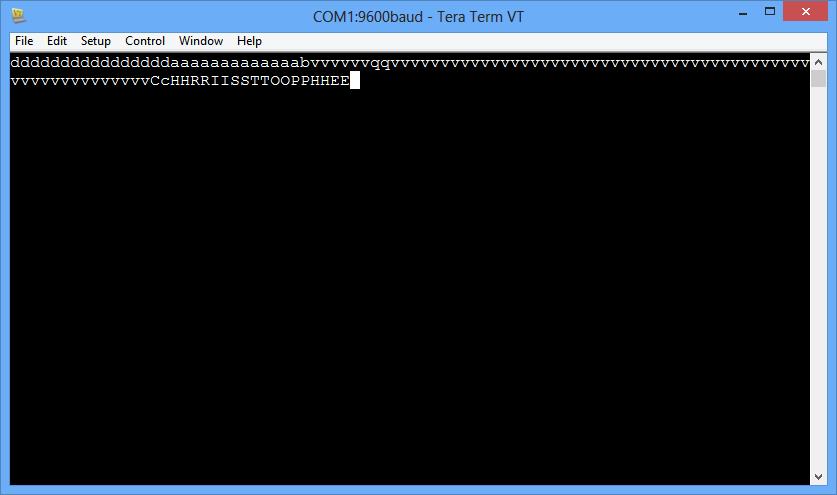
An adapter is needed to convert PC serial port to 3.3V
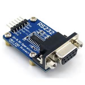
PC serial to 3.3V MAX3232 adapter