| 1 |
3 |
howe.r.j.8 |
# Forth computing system
|
| 2 |
|
|
|
| 3 |
|
|
| Project | Forth SoC written in VHDL |
|
| 4 |
|
|
| --------- | ------------------------- |
|
| 5 |
|
|
| Author | Richard James Howe |
|
| 6 |
5 |
howe.r.j.8 |
| Copyright | 2013-2019 Richard Howe |
|
| 7 |
3 |
howe.r.j.8 |
| License | MIT/LGPL |
|
| 8 |
|
|
| Email | howe.r.j.89@gmail.com |
|
| 9 |
|
|
|
| 10 |
|
|

|
| 11 |
|
|
|
| 12 |
|
|
# Introduction
|
| 13 |
|
|
|
| 14 |
|
|
This project implements a small stack computer tailored to executing Forth
|
| 15 |
|
|
based on the [J1][] CPU. The processor has been rewritten in [VHDL][] from
|
| 16 |
5 |
howe.r.j.8 |
[Verilog][], and extended slightly.
|
| 17 |
3 |
howe.r.j.8 |
|
| 18 |
|
|
The goals of the project are as follows:
|
| 19 |
|
|
|
| 20 |
|
|
* Create a working version of [J1][] processor (called the H2).
|
| 21 |
|
|
* Make a working toolchain for the processor.
|
| 22 |
|
|
* Create a [FORTH][] for the processor which can take its input either from a
|
| 23 |
|
|
[UART][] or a USB keyboard and a [VGA][] adapter.
|
| 24 |
|
|
|
| 25 |
5 |
howe.r.j.8 |
All three of which have been completed.
|
| 26 |
|
|
|
| 27 |
3 |
howe.r.j.8 |
The H2 processor, like the [J1][], is a stack based processor that executes an
|
| 28 |
|
|
instruction set especially suited for [FORTH][].
|
| 29 |
|
|
|
| 30 |
|
|
The current target is the [Nexys3][] board, with a [Xilinx][] Spartan-6 XC6LX16-CS324
|
| 31 |
|
|
[FPGA][], new boards will be targeted in the future as this board is reaching it's
|
| 32 |
|
|
end of life. The [VHDL][] is written in a generic way, with hardware components
|
| 33 |
|
|
being inferred instead of explicitly instantiated, this should make the code
|
| 34 |
|
|
fairly portable, although the interfaces to the [Nexys3][] board components are
|
| 35 |
|
|
specific to the peripherals on that board.
|
| 36 |
|
|
|
| 37 |
|
|
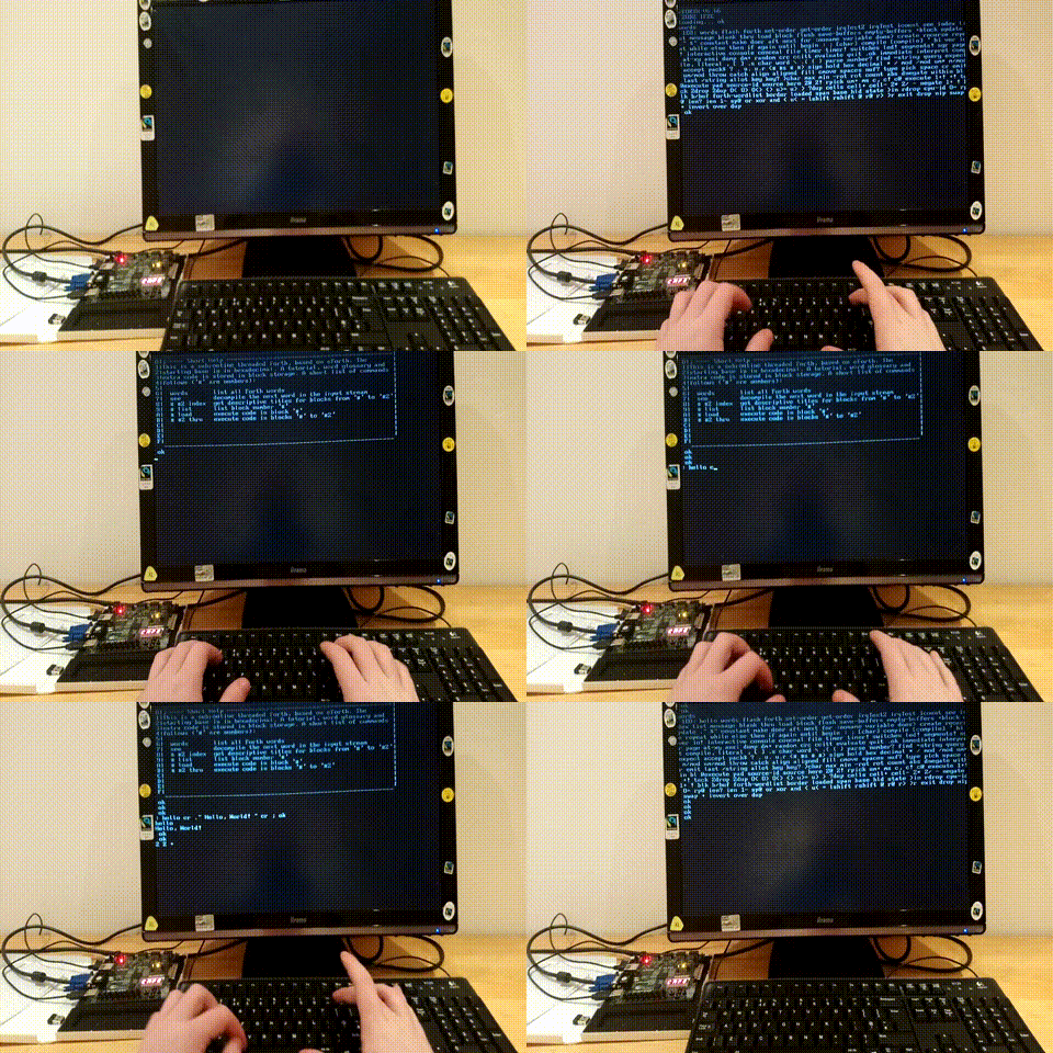
A video of the project in action, on the hardware, can be viewed here:
|
| 38 |
|
|

|
| 39 |
|
|
|
| 40 |
|
|
And a lower quality version of the same video that should play automatically:
|
| 41 |
|
|
|
| 42 |
|
|
|
| 43 |
|
|
|
| 44 |
|
|
The SoC can also be simulated with a simulator written in C, as shown below:
|
| 45 |
|
|
|
| 46 |
|
|

|
| 47 |
|
|
|
| 48 |
|
|
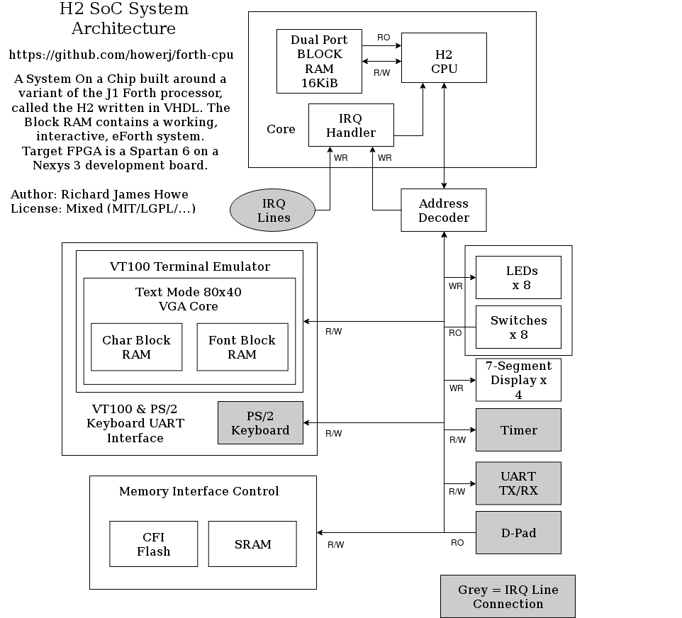
The System Architecture is as follows:
|
| 49 |
|
|
|
| 50 |
|
|
|
| 51 |
|
|
|
| 52 |
|
|
# License
|
| 53 |
|
|
|
| 54 |
|
|
The licenses used by the project are mixed and are on a per file basis. For my
|
| 55 |
|
|
code I use the [MIT][] license - so feel free to use it as you wish. The other
|
| 56 |
5 |
howe.r.j.8 |
licenses used are the [LGPL][] and the [Apache 2.0][] license, they are confined
|
| 57 |
|
|
to single modules so could be removed if you have some aversion to [LGPL][] code.
|
| 58 |
3 |
howe.r.j.8 |
|
| 59 |
|
|
# Target Board
|
| 60 |
|
|
|
| 61 |
|
|
The only target board available at the moment is the [Nexys3][], this should
|
| 62 |
|
|
change in the future as the board is currently at it's End Of Life. The next
|
| 63 |
|
|
boards I am looking to support are it's successor, the Nexys 4, and the myStorm
|
| 64 |
|
|
BlackIce (). The myStorm board uses a completely open
|
| 65 |
|
|
source toolchain for synthesis, place and route and bit file generation.
|
| 66 |
|
|
|
| 67 |
|
|
# Build and Running requirements
|
| 68 |
|
|
|
| 69 |
|
|
The build has been tested under [Debian][] [Linux][], version 8.
|
| 70 |
|
|
|
| 71 |
|
|
You will require:
|
| 72 |
|
|
|
| 73 |
|
|
* [GCC][], or a suitable [C][] compiler capable of compiling [C99][]
|
| 74 |
|
|
* [Make][]
|
| 75 |
|
|
* [Xilinx ISE][] version 14.7
|
| 76 |
|
|
* [GHDL][]
|
| 77 |
|
|
* [GTKWave][]
|
| 78 |
|
|
* [tcl][] version 8.6
|
| 79 |
|
|
* Digilent Adept2 runtime and Digilent Adept2 utilities available at
|
| 80 |
|
|
|
| 81 |
|
|
* [freeglut][] (for the GUI simulator only)
|
| 82 |
|
|
* [pandoc][] for building the documentation
|
| 83 |
|
|
* [picocom][] (or an alternative terminal client)
|
| 84 |
|
|
|
| 85 |
|
|
Hardware:
|
| 86 |
|
|
|
| 87 |
5 |
howe.r.j.8 |
* VGA Monitor, and cable (Optional)
|
| 88 |
|
|
* USB Keyboard (Optional) (plugs into the Nexys3 USB to PS/2 bridge)
|
| 89 |
|
|
* [Nexys3][] development board (if communication via UART only is
|
| 90 |
|
|
desired, the VGA Monitor and USB and Keyboard are not needed).
|
| 91 |
|
|
* USB Cables!
|
| 92 |
3 |
howe.r.j.8 |
|
| 93 |
|
|
[Xilinx ISE][] can (or could be) downloaded for free, but requires
|
| 94 |
|
|
registration. ISE needs to be on your path:
|
| 95 |
|
|
|
| 96 |
|
|
PATH=$PATH:/opt/Xilinx/14.7/ISE_DS/ISE/bin/lin64;
|
| 97 |
|
|
PATH=$PATH:/opt/Xilinx/14.7/ISE_DS/ISE/lib/lin64;
|
| 98 |
|
|
|
| 99 |
|
|
# Building and Running
|
| 100 |
|
|
|
| 101 |
|
|
To make the [C][] based toolchain:
|
| 102 |
|
|
|
| 103 |
5 |
howe.r.j.8 |
make embed.hex
|
| 104 |
3 |
howe.r.j.8 |
|
| 105 |
|
|
To make a bit file that can be flashed to the target board:
|
| 106 |
|
|
|
| 107 |
|
|
make simulation synthesis implementation bitfile
|
| 108 |
|
|
|
| 109 |
|
|
To upload the bitfile to the target board:
|
| 110 |
|
|
|
| 111 |
|
|
make upload
|
| 112 |
|
|
|
| 113 |
|
|
To view the wave form generated by "make simulation":
|
| 114 |
|
|
|
| 115 |
|
|
make viewer
|
| 116 |
|
|
|
| 117 |
|
|
The [C][] based CLI simulator can be invoked with:
|
| 118 |
|
|
|
| 119 |
|
|
make run
|
| 120 |
|
|
|
| 121 |
5 |
howe.r.j.8 |
Which will assemble the H2 Forth source file [embed.fth][], and run the assembled
|
| 122 |
3 |
howe.r.j.8 |
object file under the H2 simulator with the debugger activated. A graphical
|
| 123 |
|
|
simulator can be run with:
|
| 124 |
|
|
|
| 125 |
|
|
make gui-run
|
| 126 |
|
|
|
| 127 |
|
|
Which requires [freeglut][] as well as a [C][] compiler.
|
| 128 |
|
|
|
| 129 |
|
|
# Related Projects
|
| 130 |
|
|
|
| 131 |
|
|
The original [J1][] project is available at:
|
| 132 |
|
|
|
| 133 |
|
|
*
|
| 134 |
|
|
|
| 135 |
|
|
This project targets the original [J1][] core and provides a eForth
|
| 136 |
|
|
implementation (written using [Gforth][] as for meta-compilation/cross
|
| 137 |
|
|
compilation to the [J1][] core). It also provides a simulator for the system
|
| 138 |
|
|
written in [C][].
|
| 139 |
|
|
|
| 140 |
|
|
*
|
| 141 |
|
|
|
| 142 |
5 |
howe.r.j.8 |
The eForth interpreter which the meta-compiler is built on can be found at:
|
| 143 |
3 |
howe.r.j.8 |
|
| 144 |
5 |
howe.r.j.8 |
*
|
| 145 |
|
|
|
| 146 |
3 |
howe.r.j.8 |
# Manual
|
| 147 |
|
|
|
| 148 |
5 |
howe.r.j.8 |
The H2 processor and associated peripherals are now quite stable, however the
|
| 149 |
|
|
source is always the definitive guide as to how instructions and peripherals
|
| 150 |
|
|
behave, as well as the register map.
|
| 151 |
3 |
howe.r.j.8 |
|
| 152 |
|
|
There are a few modifications to the [J1][] CPU which include:
|
| 153 |
|
|
|
| 154 |
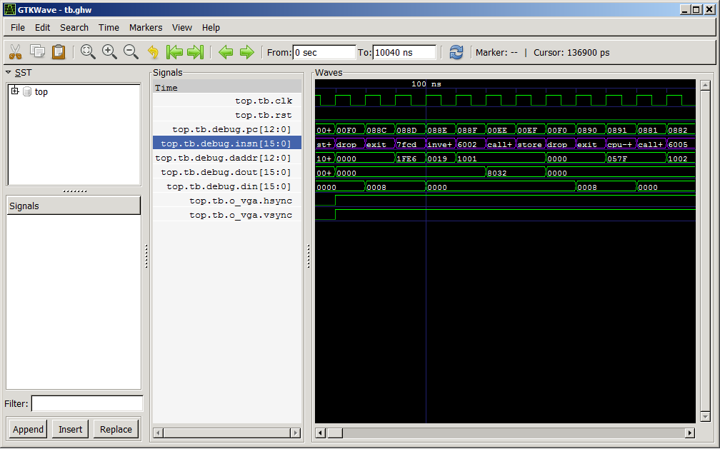
|
|
* New instructions
|
| 155 |
|
|
* A CPU hold line which keeps the processor in the same state so long as it is
|
| 156 |
|
|
high.
|
| 157 |
|
|
* Interrupt Service Routines have been added.
|
| 158 |
5 |
howe.r.j.8 |
* Larger (adjustable at time of synthesis) return and data stacks
|
| 159 |
3 |
howe.r.j.8 |
|
| 160 |
|
|
### H2 CPU
|
| 161 |
|
|
|
| 162 |
|
|
The H2 CPU behaves very similarly to the [J1][] CPU, and the [J1 PDF][] can be
|
| 163 |
|
|
read in order to better understand this processor. The processor is 16-bit with
|
| 164 |
|
|
instructions taking a single clock cycle. Most of the primitive Forth words can
|
| 165 |
|
|
also be executed in a single cycle as well, one notable exception is store ("!"),
|
| 166 |
|
|
which is split into two instructions.
|
| 167 |
|
|
|
| 168 |
|
|
The CPU has the following state within it:
|
| 169 |
|
|
|
| 170 |
|
|
* A 64 deep return stack (up from 32 in the original [J1][])
|
| 171 |
|
|
* A 65 deep variable stack (up from 33 in the original [J1][])
|
| 172 |
|
|
* A program counter
|
| 173 |
|
|
* An interrupt enable and interrupt request bit
|
| 174 |
|
|
* An interrupt address register
|
| 175 |
5 |
howe.r.j.8 |
* Registers to delay and hold the latest IRQ and hold-line values
|
| 176 |
3 |
howe.r.j.8 |
|
| 177 |
|
|
Loads and stores into the block RAM that holds the H2 program discard the
|
| 178 |
|
|
lowest bit, every other memory operation uses the lower bit (such as jumps
|
| 179 |
|
|
and loads and stores to Input/Output peripherals). This is so applications can
|
| 180 |
|
|
use the lowest bit for character operations when accessing the program RAM.
|
| 181 |
|
|
|
| 182 |
|
|
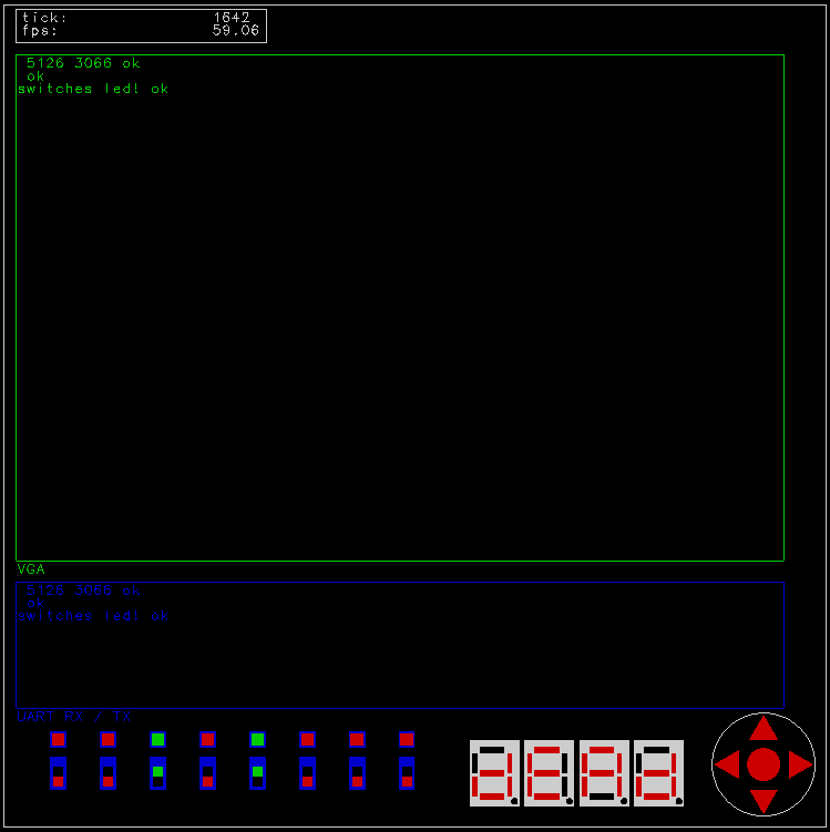
The instruction set is decoded in the following manner:
|
| 183 |
|
|
|
| 184 |
|
|
+---------------------------------------------------------------+
|
| 185 |
|
|
| F | E | D | C | B | A | 9 | 8 | 7 | 6 | 5 | 4 | 3 | 2 | 1 | 0 |
|
| 186 |
|
|
+---------------------------------------------------------------+
|
| 187 |
|
|
| 1 | LITERAL VALUE |
|
| 188 |
|
|
+---------------------------------------------------------------+
|
| 189 |
|
|
| 0 | 0 | 0 | BRANCH TARGET ADDRESS |
|
| 190 |
|
|
+---------------------------------------------------------------+
|
| 191 |
|
|
| 0 | 0 | 1 | CONDITIONAL BRANCH TARGET ADDRESS |
|
| 192 |
|
|
+---------------------------------------------------------------+
|
| 193 |
|
|
| 0 | 1 | 0 | CALL TARGET ADDRESS |
|
| 194 |
|
|
+---------------------------------------------------------------+
|
| 195 |
|
|
| 0 | 1 | 1 | ALU OPERATION |T2N|T2R|N2A|R2P| RSTACK| DSTACK|
|
| 196 |
|
|
+---------------------------------------------------------------+
|
| 197 |
|
|
| F | E | D | C | B | A | 9 | 8 | 7 | 6 | 5 | 4 | 3 | 2 | 1 | 0 |
|
| 198 |
|
|
+---------------------------------------------------------------+
|
| 199 |
|
|
|
| 200 |
|
|
T : Top of data stack
|
| 201 |
|
|
N : Next on data stack
|
| 202 |
|
|
PC : Program Counter
|
| 203 |
|
|
|
| 204 |
|
|
LITERAL VALUES : push a value onto the data stack
|
| 205 |
|
|
CONDITIONAL : BRANCHS pop and test the T
|
| 206 |
|
|
CALLS : PC+1 onto the return stack
|
| 207 |
|
|
|
| 208 |
|
|
T2N : Move T to N
|
| 209 |
|
|
T2R : Move T to top of return stack
|
| 210 |
|
|
N2A : STORE T to memory location addressed by N
|
| 211 |
|
|
R2P : Move top of return stack to PC
|
| 212 |
|
|
|
| 213 |
|
|
RSTACK and DSTACK are signed values (twos compliment) that are
|
| 214 |
|
|
the stack delta (the amount to increment or decrement the stack
|
| 215 |
|
|
by for their respective stacks: return and data)
|
| 216 |
|
|
|
| 217 |
|
|
#### ALU operations
|
| 218 |
|
|
|
| 219 |
|
|
|
| 220 |
|
|
All ALU operations replace T:
|
| 221 |
|
|
|
| 222 |
|
|
| Value | Operation | Description |
|
| 223 |
|
|
|-------|----------------|-----------------------|
|
| 224 |
|
|
| 0 | T | Top of Stack |
|
| 225 |
|
|
| 1 | N | Copy T to N |
|
| 226 |
|
|
| 2 | T + N | Addition |
|
| 227 |
|
|
| 3 | T & N | Bitwise AND |
|
| 228 |
|
|
| 4 | T or N | Bitwise OR |
|
| 229 |
|
|
| 5 | T ^ N | Bitwise XOR |
|
| 230 |
|
|
| 6 | ~T | Bitwise Inversion |
|
| 231 |
|
|
| 7 | T = N | Equality test |
|
| 232 |
|
|
| 8 | N < T | Signed comparison |
|
| 233 |
|
|
| 9 | N >> T | Logical Right Shift |
|
| 234 |
|
|
| 10 | T - 1 | Decrement |
|
| 235 |
|
|
| 11 | R | Top of return stack |
|
| 236 |
|
|
| 12 | [T] | Load from address |
|
| 237 |
|
|
| 13 | N << T | Logical Left Shift |
|
| 238 |
|
|
| 14 | depth | Depth of stack |
|
| 239 |
|
|
| 15 | N u< T | Unsigned comparison |
|
| 240 |
5 |
howe.r.j.8 |
| 16 | Set CPU State | Enable interrupts |
|
| 241 |
|
|
| 17 | Get CPU State | Are interrupts on? |
|
| 242 |
3 |
howe.r.j.8 |
| 18 | rdepth | Depth of return stk |
|
| 243 |
|
|
| 19 | 0= | T == 0? |
|
| 244 |
|
|
| 20 | CPU ID | CPU Identifier |
|
| 245 |
5 |
howe.r.j.8 |
| 21 | LITERAL | Internal Instruction |
|
| 246 |
3 |
howe.r.j.8 |
|
| 247 |
|
|
|
| 248 |
|
|
### Peripherals and registers
|
| 249 |
|
|
|
| 250 |
|
|
Registers marked prefixed with an 'o' are output registers, those with an 'i'
|
| 251 |
|
|
prefix are input registers. Registers are divided into an input and output
|
| 252 |
|
|
section of registers and the addresses of the input and output registers do not
|
| 253 |
5 |
howe.r.j.8 |
correspond to each other in all cases.
|
| 254 |
3 |
howe.r.j.8 |
|
| 255 |
|
|
The following peripherals have been implemented in the [VHDL][] SoC to
|
| 256 |
|
|
interface with devices on the [Nexys3][] board:
|
| 257 |
|
|
|
| 258 |
|
|
* [VGA][] output device, text mode only, 80 by 40 characters from
|
| 259 |
5 |
howe.r.j.8 |
. This has
|
| 260 |
|
|
been heavily modified from the original, which now implements most of a
|
| 261 |
|
|
[VT100][] terminal emulator. This has two fonts available to it:
|
| 262 |
|
|
- [Terminus][]/[KOI8-R][] (Default)
|
| 263 |
|
|
- Latin [ISO-8859-15][] (Secondary Font) from
|
| 264 |
|
|
|
| 265 |
|
|
* [Timer][] in [timer.vhd][].
|
| 266 |
|
|
* [UART][] (Rx/Tx) in [uart.vhd][].
|
| 267 |
3 |
howe.r.j.8 |
* [PS/2][] Keyboard
|
| 268 |
|
|
from
|
| 269 |
|
|
* [LED][] next to a bank of switches
|
| 270 |
5 |
howe.r.j.8 |
* A [7 Segment LED Display][] driver (a 7 segment display with a decimal point)
|
| 271 |
3 |
howe.r.j.8 |
|
| 272 |
|
|
The SoC also features a limited set of interrupts that can be enabled or
|
| 273 |
|
|
disabled.
|
| 274 |
|
|
|
| 275 |
|
|
The output register map:
|
| 276 |
|
|
|
| 277 |
|
|
| Register | Address | Description |
|
| 278 |
|
|
|-------------|---------|---------------------------------|
|
| 279 |
|
|
| oUart | 0x4000 | UART register |
|
| 280 |
|
|
| oVT100 | 0x4002 | VT100 Terminal Write |
|
| 281 |
|
|
| oLeds | 0x4004 | LED outputs |
|
| 282 |
|
|
| oTimerCtrl | 0x4006 | Timer control |
|
| 283 |
|
|
| oMemDout | 0x4008 | Memory Data Output |
|
| 284 |
|
|
| oMemControl | 0x400A | Memory Control / Hi Address |
|
| 285 |
|
|
| oMemAddrLow | 0x400C | Memory Lo Address |
|
| 286 |
5 |
howe.r.j.8 |
| o7SegLED | 0x400E | 4 x LED 7 Segment display |
|
| 287 |
3 |
howe.r.j.8 |
| oIrcMask | 0x4010 | CPU Interrupt Mask |
|
| 288 |
5 |
howe.r.j.8 |
| oUartBaudTx | 0x4012 | UART Tx Baud Clock Setting |
|
| 289 |
|
|
| oUartBaudRx | 0x4014 | UART Rx Baud Clock Setting |
|
| 290 |
3 |
howe.r.j.8 |
|
| 291 |
|
|
|
| 292 |
|
|
The input registers:
|
| 293 |
|
|
|
| 294 |
|
|
| Register | Address | Description |
|
| 295 |
|
|
|-------------|---------|---------------------------------|
|
| 296 |
|
|
| iUart | 0x4000 | UART register |
|
| 297 |
|
|
| iVT100 | 0x4002 | Terminal status & PS/2 Keyboard |
|
| 298 |
|
|
| iSwitches | 0x4004 | Buttons and switches |
|
| 299 |
|
|
| iTimerDin | 0x4006 | Current Timer Value |
|
| 300 |
|
|
| iMemDin | 0x4008 | Memory Data Input |
|
| 301 |
|
|
|
| 302 |
|
|
|
| 303 |
|
|
The following description of the registers should be read in order and describe
|
| 304 |
|
|
how the peripherals work as well.
|
| 305 |
|
|
|
| 306 |
|
|
#### oUart
|
| 307 |
|
|
|
| 308 |
|
|
A UART with a fixed baud rate and format (115200, 8 bits, 1 stop bit) is
|
| 309 |
|
|
present on the SoC. The UART has a FIFO of depth 8 on both the RX and TX
|
| 310 |
|
|
channels. The control of the UART is split across oUart and iUart.
|
| 311 |
|
|
|
| 312 |
|
|
To write a value to the UART assert TXWE along with putting the data in TXDO.
|
| 313 |
|
|
The FIFO state can be analyzed by looking at the iUart register.
|
| 314 |
|
|
|
| 315 |
|
|
To read a value from the UART: iUart can be checked to see if data is present
|
| 316 |
|
|
in the FIFO, if it is assert RXRE in the oUart register, on the next clock
|
| 317 |
|
|
cycle the data will be present in the iUart register.
|
| 318 |
|
|
|
| 319 |
|
|
The baud rate of the UART can be changed by rebuilding the VHDL project, bit
|
| 320 |
|
|
length, parity bits and stop bits can only be changed with modifications to
|
| 321 |
|
|
[uart.vhd][]
|
| 322 |
|
|
|
| 323 |
|
|
+-------------------------------------------------------------------------------+
|
| 324 |
|
|
| 15 | 14 | 13 | 12 | 11 | 10 | 9 | 8 | 7 | 6 | 5 | 4 | 3 | 2 | 1 | 0 |
|
| 325 |
|
|
+-------------------------------------------------------------------------------+
|
| 326 |
|
|
| X | X |TXWE| X | X |RXRE| X | X | TXDO |
|
| 327 |
|
|
+-------------------------------------------------------------------------------+
|
| 328 |
|
|
|
| 329 |
|
|
TXWE: UART TX Write Enable
|
| 330 |
|
|
RXRE: UART RX Read Enable
|
| 331 |
|
|
TXDO: UART TX Data Output
|
| 332 |
|
|
|
| 333 |
|
|
#### oVT100
|
| 334 |
|
|
|
| 335 |
|
|
The VGA Text device emulates a terminal which the user can talk to by writing
|
| 336 |
|
|
to the oVT100 register. It supports a subset of the [VT100][] terminal
|
| 337 |
|
|
functionality. The interface behaves much like writing to a UART with the same
|
| 338 |
|
|
busy and control signals. The input is taken from a [PS/2][] keyboard available
|
| 339 |
|
|
on the board, this behaves like the RX mechanism of the UART.
|
| 340 |
|
|
|
| 341 |
|
|
+-------------------------------------------------------------------------------+
|
| 342 |
|
|
| 15 | 14 | 13 | 12 | 11 | 10 | 9 | 8 | 7 | 6 | 5 | 4 | 3 | 2 | 1 | 0 |
|
| 343 |
|
|
+-------------------------------------------------------------------------------+
|
| 344 |
|
|
| X | X |TXWE| X | X |RXRE| X | X | TXDO |
|
| 345 |
|
|
+-------------------------------------------------------------------------------+
|
| 346 |
|
|
|
| 347 |
|
|
TXWE: VT100 TX Write Enable
|
| 348 |
|
|
RXRE: UART RX Read Enable
|
| 349 |
|
|
TXDO: UART TX Data Output
|
| 350 |
|
|
|
| 351 |
|
|
#### oLeds
|
| 352 |
|
|
|
| 353 |
|
|
On the [Nexys3][] board there is a bank of LEDs that are situated next to the
|
| 354 |
|
|
switches, these LEDs can be turned on (1) or off (0) by writing to LEDO. Each
|
| 355 |
|
|
LED here corresponds to the switch it is next to.
|
| 356 |
|
|
|
| 357 |
|
|
+-------------------------------------------------------------------------------+
|
| 358 |
|
|
| 15 | 14 | 13 | 12 | 11 | 10 | 9 | 8 | 7 | 6 | 5 | 4 | 3 | 2 | 1 | 0 |
|
| 359 |
|
|
+-------------------------------------------------------------------------------+
|
| 360 |
|
|
| X | X | X | X | X | X | X | X | LEDO |
|
| 361 |
|
|
+-------------------------------------------------------------------------------+
|
| 362 |
|
|
|
| 363 |
|
|
LEDO: LED Output
|
| 364 |
|
|
|
| 365 |
|
|
#### oTimerCtrl
|
| 366 |
|
|
|
| 367 |
|
|
The timer is controllable by the oTimerCtrl register, it is a 13-bit timer
|
| 368 |
|
|
running at 100MHz, it can optionally generate interrupts and the current timers
|
| 369 |
|
|
internal count can be read back in with the iTimerDin register.
|
| 370 |
|
|
|
| 371 |
|
|
The timer counts once the TE bit is asserted, once the timer reaches TCMP value
|
| 372 |
|
|
it wraps around and can optionally generate an interrupt by asserting INTE.
|
| 373 |
|
|
This also toggles the Q and NQ lines that come out of the timer and are routed
|
| 374 |
|
|
to pins on the board (see the constraints file [top.ucf][] for the pins).
|
| 375 |
|
|
|
| 376 |
|
|
The timer can be reset by writing to RST.
|
| 377 |
|
|
|
| 378 |
|
|
+-------------------------------------------------------------------------------+
|
| 379 |
|
|
| 15 | 14 | 13 | 12 | 11 | 10 | 9 | 8 | 7 | 6 | 5 | 4 | 3 | 2 | 1 | 0 |
|
| 380 |
|
|
+-------------------------------------------------------------------------------+
|
| 381 |
|
|
| TE | RST|INTE| TCMP |
|
| 382 |
|
|
+-------------------------------------------------------------------------------+
|
| 383 |
|
|
|
| 384 |
|
|
TE: Timer Enable
|
| 385 |
|
|
RST: Timer Reset
|
| 386 |
|
|
INTE: Interrupt Enable
|
| 387 |
|
|
TCMP: Timer Compare Value
|
| 388 |
|
|
|
| 389 |
|
|
|
| 390 |
|
|
#### oIrcMask
|
| 391 |
|
|
|
| 392 |
|
|
The H2 core has a mechanism for interrupts, interrupts have to be enabled or
|
| 393 |
|
|
disabled with an instruction. Each interrupt can be masked off with a bit in
|
| 394 |
|
|
IMSK to enable that specific interrupt. A '1' in a bit of IMSK enables that
|
| 395 |
|
|
specific interrupt, which will be delivered to the CPU if interrupts are
|
| 396 |
|
|
enabled within it.
|
| 397 |
|
|
|
| 398 |
|
|
+-------------------------------------------------------------------------------+
|
| 399 |
|
|
| 15 | 14 | 13 | 12 | 11 | 10 | 9 | 8 | 7 | 6 | 5 | 4 | 3 | 2 | 1 | 0 |
|
| 400 |
|
|
+-------------------------------------------------------------------------------+
|
| 401 |
|
|
| X | X | X | X | X | X | X | X | IMSK |
|
| 402 |
|
|
+-------------------------------------------------------------------------------+
|
| 403 |
|
|
|
| 404 |
|
|
IMSK: Interrupt Mask
|
| 405 |
|
|
|
| 406 |
5 |
howe.r.j.8 |
#### oUartBaudTx
|
| 407 |
|
|
|
| 408 |
|
|
This register is used to set the baud and sample clock frequency for
|
| 409 |
|
|
transmission only.
|
| 410 |
|
|
|
| 411 |
|
|
+-------------------------------------------------------------------------------+
|
| 412 |
|
|
| 15 | 14 | 13 | 12 | 11 | 10 | 9 | 8 | 7 | 6 | 5 | 4 | 3 | 2 | 1 | 0 |
|
| 413 |
|
|
+-------------------------------------------------------------------------------+
|
| 414 |
|
|
| BTXC |
|
| 415 |
|
|
+-------------------------------------------------------------------------------+
|
| 416 |
|
|
|
| 417 |
|
|
BTXC: Baud Clock Settings
|
| 418 |
|
|
|
| 419 |
|
|
#### oUartBaudRx
|
| 420 |
|
|
|
| 421 |
|
|
This register is used to set the baud and sample clock frequency for
|
| 422 |
|
|
reception only.
|
| 423 |
|
|
|
| 424 |
|
|
+-------------------------------------------------------------------------------+
|
| 425 |
|
|
| 15 | 14 | 13 | 12 | 11 | 10 | 9 | 8 | 7 | 6 | 5 | 4 | 3 | 2 | 1 | 0 |
|
| 426 |
|
|
+-------------------------------------------------------------------------------+
|
| 427 |
|
|
| BRXC |
|
| 428 |
|
|
+-------------------------------------------------------------------------------+
|
| 429 |
|
|
|
| 430 |
|
|
BRXC: Baud Clock Settings
|
| 431 |
|
|
|
| 432 |
|
|
|
| 433 |
3 |
howe.r.j.8 |
#### oMemDout
|
| 434 |
|
|
|
| 435 |
|
|
Data to be output to selected address when write enable (WE) issued in
|
| 436 |
|
|
oMemControl.
|
| 437 |
|
|
|
| 438 |
|
|
+-------------------------------------------------------------------------------+
|
| 439 |
|
|
| 15 | 14 | 13 | 12 | 11 | 10 | 9 | 8 | 7 | 6 | 5 | 4 | 3 | 2 | 1 | 0 |
|
| 440 |
|
|
+-------------------------------------------------------------------------------+
|
| 441 |
|
|
| Data Ouput |
|
| 442 |
|
|
+-------------------------------------------------------------------------------+
|
| 443 |
|
|
|
| 444 |
|
|
#### oMemControl
|
| 445 |
|
|
|
| 446 |
|
|
This register contains the control registers for the onboard memory on the
|
| 447 |
|
|
[Nexys3][] board. The board contains three memory devices, two non-volatile
|
| 448 |
|
|
memory devices and a volatile RAM based device. The two devices accessible by a
|
| 449 |
|
|
simple SRAM interface (one volatile M45W8MW16, one non-volatile - a
|
| 450 |
|
|
NP8P128A13T1760E) are both accessible, the third is an SPI based memory device,
|
| 451 |
|
|
NP5Q128A13ESFC0E) and is currently not accessible.
|
| 452 |
|
|
|
| 453 |
|
|
+-------------------------------------------------------------------------------+
|
| 454 |
|
|
| 15 | 14 | 13 | 12 | 11 | 10 | 9 | 8 | 7 | 6 | 5 | 4 | 3 | 2 | 1 | 0 |
|
| 455 |
|
|
+-------------------------------------------------------------------------------+
|
| 456 |
|
|
| OE | WE | RST|WAIT| RCS| FCS| Address Hi |
|
| 457 |
|
|
+-------------------------------------------------------------------------------+
|
| 458 |
|
|
|
| 459 |
|
|
OE: Output Enable - enable reading from current address into iMemDin
|
| 460 |
|
|
WE: Write Enable - enable writing oMemDout into ram at current address
|
| 461 |
|
|
RST: Reset the Flash memory controller
|
| 462 |
|
|
RCS: RAM Chip Select, Enable Volatile Memory
|
| 463 |
|
|
FCS: Flash Chip Select, Enable Non-Volatile Memory
|
| 464 |
|
|
Address Hi: High Bits of RAM address
|
| 465 |
|
|
|
| 466 |
|
|
OE and WE are mutually exclusive, if both are set then there is no effect.
|
| 467 |
|
|
|
| 468 |
|
|
The memory controller is in active development, and the interface to it might
|
| 469 |
|
|
change.
|
| 470 |
|
|
|
| 471 |
|
|
#### oMemAddrLow
|
| 472 |
|
|
|
| 473 |
|
|
This is the lower address bits of the RAM.
|
| 474 |
|
|
|
| 475 |
|
|
+-------------------------------------------------------------------------------+
|
| 476 |
|
|
| 15 | 14 | 13 | 12 | 11 | 10 | 9 | 8 | 7 | 6 | 5 | 4 | 3 | 2 | 1 | 0 |
|
| 477 |
|
|
+-------------------------------------------------------------------------------+
|
| 478 |
|
|
| Address Lo |
|
| 479 |
|
|
+-------------------------------------------------------------------------------+
|
| 480 |
|
|
|
| 481 |
|
|
#### o7SegLED
|
| 482 |
|
|
|
| 483 |
5 |
howe.r.j.8 |
On the [Nexys3][] board there is a bank of 7 segment displays, with a decimal
|
| 484 |
|
|
point (8-segment really), which can be used for numeric output. The LED segments
|
| 485 |
3 |
howe.r.j.8 |
cannot be directly addressed. Instead the value stored in L8SD is mapped
|
| 486 |
|
|
to a hexadecimal display value (or a BCD value, but this requires regeneration
|
| 487 |
|
|
of the SoC and modification of a generic in the VHDL).
|
| 488 |
|
|
|
| 489 |
|
|
The value '0' corresponds to a zero displayed on the LED segment, '15' to an
|
| 490 |
|
|
'F', etcetera.
|
| 491 |
|
|
|
| 492 |
|
|
There are 4 displays in a row.
|
| 493 |
|
|
|
| 494 |
|
|
+-------------------------------------------------------------------------------+
|
| 495 |
|
|
| 15 | 14 | 13 | 12 | 11 | 10 | 9 | 8 | 7 | 6 | 5 | 4 | 3 | 2 | 1 | 0 |
|
| 496 |
|
|
+-------------------------------------------------------------------------------+
|
| 497 |
|
|
| L7SD0 | L7SD1 | L7SD2 | L7SD3 |
|
| 498 |
|
|
+-------------------------------------------------------------------------------+
|
| 499 |
|
|
|
| 500 |
|
|
L7SD0: LED 7 Segment Display (leftmost display)
|
| 501 |
|
|
L7SD1: LED 7 Segment Display
|
| 502 |
|
|
L7SD2: LED 7 Segment Display
|
| 503 |
|
|
L7SD3: LED 7 Segment Display (right most display)
|
| 504 |
|
|
|
| 505 |
|
|
#### iUart
|
| 506 |
|
|
|
| 507 |
|
|
The iUart register works in conjunction with the oUart register. The status of
|
| 508 |
|
|
the FIFO that buffers both transmission and reception of bytes is available in
|
| 509 |
|
|
the iUart register, as well as any received bytes.
|
| 510 |
|
|
|
| 511 |
|
|
+-------------------------------------------------------------------------------+
|
| 512 |
|
|
| 15 | 14 | 13 | 12 | 11 | 10 | 9 | 8 | 7 | 6 | 5 | 4 | 3 | 2 | 1 | 0 |
|
| 513 |
|
|
+-------------------------------------------------------------------------------+
|
| 514 |
|
|
| X | X | X |TFFL|TFEM| X |RFFL|RFEM| RXDI |
|
| 515 |
|
|
+-------------------------------------------------------------------------------+
|
| 516 |
|
|
|
| 517 |
|
|
TFFL: UART TX FIFO Full
|
| 518 |
|
|
TFEM: UART TX FIFO Empty
|
| 519 |
|
|
RFFL: UART RX FIFO Full
|
| 520 |
|
|
RFEM: UART RX FIFO Empty
|
| 521 |
|
|
RXDI: UART RX Data Input
|
| 522 |
|
|
|
| 523 |
|
|
#### iVT100
|
| 524 |
|
|
|
| 525 |
|
|
The iVT100 register works in conjunction with the oVT100 register. The status of
|
| 526 |
|
|
the FIFO that buffers both transmission and reception of bytes is available in
|
| 527 |
|
|
the iVT100 register, as well as any received bytes. It works the same as the
|
| 528 |
|
|
iUart/oUart registers.
|
| 529 |
|
|
|
| 530 |
|
|
+-------------------------------------------------------------------------------+
|
| 531 |
|
|
| 15 | 14 | 13 | 12 | 11 | 10 | 9 | 8 | 7 | 6 | 5 | 4 | 3 | 2 | 1 | 0 |
|
| 532 |
|
|
+-------------------------------------------------------------------------------+
|
| 533 |
|
|
| X | X | X |TFFL|TFEM| X |RFFL|RFEM| 0 | ACHR |
|
| 534 |
|
|
+-------------------------------------------------------------------------------+
|
| 535 |
|
|
|
| 536 |
|
|
TFFL: VGA VT100 TX FIFO Full
|
| 537 |
|
|
TFEM: VGA VT100 TX FIFO Empty
|
| 538 |
|
|
RFFL: PS2 VT100 RX FIFO Full
|
| 539 |
|
|
RFEM: PS2 VT100 RX FIFO Empty
|
| 540 |
|
|
ACHR: New character available on PS2 Keyboard
|
| 541 |
|
|
|
| 542 |
|
|
#### iTimerDin
|
| 543 |
|
|
|
| 544 |
|
|
This register contains the current value of the timers counter.
|
| 545 |
|
|
|
| 546 |
|
|
+-------------------------------------------------------------------------------+
|
| 547 |
|
|
| 15 | 14 | 13 | 12 | 11 | 10 | 9 | 8 | 7 | 6 | 5 | 4 | 3 | 2 | 1 | 0 |
|
| 548 |
|
|
+-------------------------------------------------------------------------------+
|
| 549 |
|
|
| X | X | X | TCNT |
|
| 550 |
|
|
+-------------------------------------------------------------------------------+
|
| 551 |
|
|
|
| 552 |
|
|
TCNT: Timer Counter Value
|
| 553 |
|
|
|
| 554 |
|
|
#### iSwitches
|
| 555 |
|
|
|
| 556 |
|
|
iSwitches contains input lines from multiple sources. The buttons
|
| 557 |
|
|
(BUP, BDWN, BLFT, BRGH, and BCNT) correspond to a [D-Pad][] on the [Nexys3][]
|
| 558 |
|
|
board. The switches (TSWI) are the ones mentioned in oLeds, each have an LED
|
| 559 |
|
|
next to them.
|
| 560 |
|
|
|
| 561 |
|
|
The switches and the buttons are already debounced in hardware so they do not
|
| 562 |
|
|
have to be further processed once read in from these registers.
|
| 563 |
|
|
|
| 564 |
|
|
+-------------------------------------------------------------------------------+
|
| 565 |
|
|
| 15 | 14 | 13 | 12 | 11 | 10 | 9 | 8 | 7 | 6 | 5 | 4 | 3 | 2 | 1 | 0 |
|
| 566 |
|
|
+-------------------------------------------------------------------------------+
|
| 567 |
|
|
| X | X | X | BUP|BDWN|BLFT|BRGH|BCNT| TSWI |
|
| 568 |
|
|
+-------------------------------------------------------------------------------+
|
| 569 |
|
|
|
| 570 |
|
|
BUP: Button Up
|
| 571 |
|
|
BDWN: Button Down
|
| 572 |
|
|
BLFT: Button Left
|
| 573 |
|
|
BRGH: Button Right
|
| 574 |
|
|
BCNT: Button Center
|
| 575 |
|
|
TSWI: Two Position Switches
|
| 576 |
|
|
|
| 577 |
|
|
#### iMemDin
|
| 578 |
|
|
|
| 579 |
|
|
Memory input, either from the SRAM or Flash, indexed by oMemControl and
|
| 580 |
|
|
oMemAddrLow. When reading from flash this might actually be status information
|
| 581 |
|
|
or information from the query table.
|
| 582 |
|
|
|
| 583 |
|
|
+-------------------------------------------------------------------------------+
|
| 584 |
|
|
| 15 | 14 | 13 | 12 | 11 | 10 | 9 | 8 | 7 | 6 | 5 | 4 | 3 | 2 | 1 | 0 |
|
| 585 |
|
|
+-------------------------------------------------------------------------------+
|
| 586 |
|
|
| Data Input |
|
| 587 |
|
|
+-------------------------------------------------------------------------------+
|
| 588 |
|
|
|
| 589 |
|
|
|
| 590 |
|
|
### Interrupt Service Routines
|
| 591 |
|
|
|
| 592 |
|
|
The following interrupt service routines are defined:
|
| 593 |
|
|
|
| 594 |
|
|
| Name | Number | Description |
|
| 595 |
|
|
|-------------------|--------|-------------------------------|
|
| 596 |
|
|
| isrNone | 0 | Not used |
|
| 597 |
|
|
| isrRxFifoNotEmpty | 1 | UART RX FIFO Is Not Empty |
|
| 598 |
|
|
| isrRxFifoFull | 2 | UART RX FIFI Is Full |
|
| 599 |
|
|
| isrTxFifoNotEmpty | 3 | UART TX FIFO Is Not Empty |
|
| 600 |
|
|
| isrTxFifoFull | 4 | UART TX FIFO Is Full |
|
| 601 |
|
|
| isrKbdNew | 5 | New PS/2 Keyboard Character |
|
| 602 |
|
|
| isrTimer | 6 | Timer Counter |
|
| 603 |
|
|
| isrDPadButton | 7 | Any D-Pad Button Change State |
|
| 604 |
|
|
|
| 605 |
|
|
|
| 606 |
|
|
When an interrupt occurs, and interrupts are enabled within the processor, then
|
| 607 |
|
|
a call to the location in memory is performed - the location is the same as the
|
| 608 |
|
|
ISR number. An ISR with a number of '4' will perform a call (not a jump) to the
|
| 609 |
|
|
location '4' within memory, for example.
|
| 610 |
|
|
|
| 611 |
|
|
Interrupts have a latency of at least 4-5 cycles before they are acted on, there
|
| 612 |
|
|
is a two to three cycle delay in the interrupt request handler, then the call
|
| 613 |
|
|
to the ISR location in memory has to be done, then the call to the word that
|
| 614 |
|
|
implements the ISR itself.
|
| 615 |
|
|
|
| 616 |
|
|
If two interrupts occur at the same time they are processed from the lowest
|
| 617 |
|
|
interrupt number to the highest.
|
| 618 |
|
|
|
| 619 |
|
|
Interrupts are lost when an interrupt with the same number occurs that has not
|
| 620 |
|
|
been processed.
|
| 621 |
|
|
|
| 622 |
|
|
# The Toolchain
|
| 623 |
|
|
|
| 624 |
5 |
howe.r.j.8 |
The Disassembler and [C][] based simulator for the H2 is in a single
|
| 625 |
3 |
howe.r.j.8 |
program (see [h2.c][]). This simulator complements the [VHDL][] test bench
|
| 626 |
5 |
howe.r.j.8 |
[tb.vhd][] and is not a replacement for it. The meta-compiler runs on top of an
|
| 627 |
|
|
eForth interpreter and it contained within the files [embed.c][] and
|
| 628 |
|
|
[embed.blk][]. The meta-compiler (Forth parlance for a cross-compiler) is a
|
| 629 |
|
|
Forth program which is used to create the eForth image that runs on the target.
|
| 630 |
3 |
howe.r.j.8 |
|
| 631 |
5 |
howe.r.j.8 |
The toolchain is currently in flux, going forward there is liable to more
|
| 632 |
|
|
integration between [h2.c][] and [embed.c][], along with changing the Embed
|
| 633 |
|
|
Virtual Machine into one that more closely resembles the H2 CPU with the long
|
| 634 |
|
|
term goal of creating a self hosting system.
|
| 635 |
3 |
howe.r.j.8 |
|
| 636 |
5 |
howe.r.j.8 |
To build both, a [C][] compiler is needed, the build target "h2" will build the
|
| 637 |
|
|
executable, h2, and "embed" will build the meta-compiler:
|
| 638 |
3 |
howe.r.j.8 |
|
| 639 |
5 |
howe.r.j.8 |
make h2 embed
|
| 640 |
3 |
howe.r.j.8 |
|
| 641 |
5 |
howe.r.j.8 |
And it can be run on the source file [embed.fth][] with the make target:
|
| 642 |
|
|
|
| 643 |
3 |
howe.r.j.8 |
make run
|
| 644 |
|
|
|
| 645 |
|
|
The make file is not needed:
|
| 646 |
|
|
|
| 647 |
|
|
Linux:
|
| 648 |
|
|
|
| 649 |
5 |
howe.r.j.8 |
cc -std=c99 h2.c -o h2 # To build the h2 executable
|
| 650 |
|
|
cc -std=c99 embed.c -o embed # To build the embed VM executable
|
| 651 |
|
|
./embed embed.blk embed.hex embed.fth # Create the target eForth image
|
| 652 |
|
|
./h2 -h # For a list of options
|
| 653 |
|
|
./h2 -r embed.hex # Run the assembled file
|
| 654 |
3 |
howe.r.j.8 |
|
| 655 |
|
|
Windows:
|
| 656 |
|
|
|
| 657 |
5 |
howe.r.j.8 |
gcc -std=c99 h2.c -o h2.exe # Builds the h2.exe executable
|
| 658 |
|
|
gcc -std=c99 embed.c -o embed.exe # Builds the embed.exe executable
|
| 659 |
|
|
embed.exe embed.blk embed.hex embed.fth # Create the target eForth iamge
|
| 660 |
3 |
howe.r.j.8 |
h2.exe -h # For a list of options
|
| 661 |
5 |
howe.r.j.8 |
h2.exe -r embed.hex # Run the assembled file
|
| 662 |
3 |
howe.r.j.8 |
|
| 663 |
|
|
A list of command line options available:
|
| 664 |
|
|
|
| 665 |
|
|
- stop processing options, following arguments are files
|
| 666 |
|
|
-h print a help message and exit
|
| 667 |
|
|
-v increase logging level
|
| 668 |
|
|
-d disassemble input files (default)
|
| 669 |
|
|
-D full disassembly of input files
|
| 670 |
|
|
-T Enter debug mode when running simulation
|
| 671 |
|
|
-r run hex file
|
| 672 |
|
|
-L # load symbol file
|
| 673 |
|
|
-s # number of steps to run simulation (0 = forever)
|
| 674 |
|
|
-n # specify NVRAM block file (default is nvram.blk)
|
| 675 |
|
|
file* file to process
|
| 676 |
|
|
|
| 677 |
|
|
This program is released under the [MIT][] license, feel free to use it and
|
| 678 |
|
|
modify it as you please. With minimal modification it should be able to
|
| 679 |
|
|
assemble programs for the original [J1][] core.
|
| 680 |
|
|
|
| 681 |
5 |
howe.r.j.8 |
## Meta-Compiler
|
| 682 |
3 |
howe.r.j.8 |
|
| 683 |
5 |
howe.r.j.8 |
The meta-compiler runs on top of the [embed][] virtual machine, it is a 16-bit
|
| 684 |
|
|
virtual machine that originally descended from the H2 CPU. The project includes
|
| 685 |
|
|
a meta-compilation scheme that allows an eForth image to generate a new eForth
|
| 686 |
|
|
image with modifications. That system has been adapted for use with the H2,
|
| 687 |
|
|
which replaced the cross compiler written in C, which allowed the first image
|
| 688 |
|
|
for the H2 to be created.
|
| 689 |
3 |
howe.r.j.8 |
|
| 690 |
5 |
howe.r.j.8 |
The meta-compiler is an ordinary Forth program, it is contained within
|
| 691 |
|
|
[embed.fth][]. The meta-compiler Forth program is then used to build up an
|
| 692 |
|
|
eForth image capable of running on the H2 target.
|
| 693 |
3 |
howe.r.j.8 |
|
| 694 |
5 |
howe.r.j.8 |
For more information about meta-compilation in Forth, see:
|
| 695 |
3 |
howe.r.j.8 |
|
| 696 |
5 |
howe.r.j.8 |
*
|
| 697 |
|
|
*
|
| 698 |
|
|
*
|
| 699 |
3 |
howe.r.j.8 |
|
| 700 |
|
|
## Disassembler
|
| 701 |
|
|
|
| 702 |
|
|
The disassembler takes a text file containing the assembled program, which
|
| 703 |
|
|
consists of 16-bit hexadecimal numbers. It then attempts to disassemble the
|
| 704 |
|
|
instructions. It can also be fed a symbols file which can be generated by the
|
| 705 |
|
|
assembler and attempt to find the locations jumps and calls point to.
|
| 706 |
|
|
|
| 707 |
|
|
The disassembler is used by a [tcl][] script called by [GTKwave][], it
|
| 708 |
|
|
turns the instruction trace of the H2 from a series of numbers into the
|
| 709 |
|
|
instructions and branch destinations that they represent. This makes debugging
|
| 710 |
|
|
the VHDL much easier.
|
| 711 |
|
|
|
| 712 |
|
|
|
| 713 |
|
|
|
| 714 |
|
|
The purple trace shows the disassembled instructions.
|
| 715 |
|
|
|
| 716 |
|
|
## Simulator
|
| 717 |
|
|
|
| 718 |
|
|
The simulator in C implements the H2 core and most of the SoC. The IO for the
|
| 719 |
5 |
howe.r.j.8 |
simulator is not cycle accurate, but can be used for running and debugging
|
| 720 |
|
|
programs with results that are very similar to how the hardware behaves.
|
| 721 |
|
|
This is much faster than rebuilding the bit file used to flash the [FPGA][].
|
| 722 |
3 |
howe.r.j.8 |
|
| 723 |
|
|
## Debugger
|
| 724 |
|
|
|
| 725 |
|
|
The simulator also includes a debugger, which is designed to be similar to the
|
| 726 |
|
|
[DEBUG.COM][] program available in [DOS][]. The debugger can be used to
|
| 727 |
|
|
disassemble sections of memory, inspect the status of the peripherals and dump
|
| 728 |
|
|
sections of memory to the screen. It can also be used to set breakpoints,
|
| 729 |
|
|
single step and run through the code until a breakpoint is hit.
|
| 730 |
|
|
|
| 731 |
|
|
To run the debugger either a hex file or a source file must be given:
|
| 732 |
|
|
|
| 733 |
|
|
# -T turns debugging mode on
|
| 734 |
|
|
./h2 -T -r file.hex # Run simulator
|
| 735 |
|
|
|
| 736 |
|
|
Both modes of operation can be augmented with a symbols file, which lists where
|
| 737 |
|
|
variables, labels and functions are located with the assembled core.
|
| 738 |
|
|
|
| 739 |
|
|
When the "-T" option is given debug mode will be entered before the simulation
|
| 740 |
|
|
is executed. A prompt should appear and the command line should look like this:
|
| 741 |
|
|
|
| 742 |
|
|
$ ./h2 -T -R h2.fth
|
| 743 |
|
|
Debugger running, type 'h' for a list of command
|
| 744 |
|
|
debug>
|
| 745 |
|
|
|
| 746 |
|
|
Break points can be set either symbolically or by program location, the 'b'
|
| 747 |
|
|
command is used to set breakpoints:
|
| 748 |
|
|
|
| 749 |
|
|
Numbers can be entered in octal (prefix the number with '0'), hexadecimal
|
| 750 |
|
|
(prefix with '0x') or in decimal. As an example, the following three debug
|
| 751 |
|
|
commands all set a breakpoint at the same location:
|
| 752 |
|
|
|
| 753 |
|
|
debug> b 16
|
| 754 |
|
|
debug> b 0x10
|
| 755 |
|
|
debug> b 020
|
| 756 |
|
|
|
| 757 |
|
|
'k' can be used to list the current break points that are set:
|
| 758 |
|
|
|
| 759 |
|
|
debug> k
|
| 760 |
|
|
0x0010
|
| 761 |
|
|
|
| 762 |
|
|
This sets a breakpoint when the function "key?" is called:
|
| 763 |
|
|
|
| 764 |
|
|
debug> b key?
|
| 765 |
|
|
|
| 766 |
|
|
Functions and labels can both be halted on, this requires either a
|
| 767 |
|
|
symbols file to be specified on the command line or assemble and run
|
| 768 |
|
|
to be used on a source file, not a hex file. Symbol files can be used
|
| 769 |
|
|
on source or on hex files.
|
| 770 |
|
|
|
| 771 |
|
|
To single step the 's' command can be given, although not much will happen if
|
| 772 |
|
|
tracing is turned off (tracing is off by default). Tracing can be toggled on or
|
| 773 |
|
|
off with the 't' command:
|
| 774 |
|
|
|
| 775 |
|
|
debug> s
|
| 776 |
|
|
debug> s
|
| 777 |
|
|
debug> t
|
| 778 |
|
|
trace on
|
| 779 |
|
|
debug> s
|
| 780 |
|
|
0001: pc(089a) inst(4889) sp(0) rp(0) tos(0000) r(0000) call 889 init
|
| 781 |
|
|
debug> s
|
| 782 |
|
|
0002: pc(0889) inst(807a) sp(0) rp(1) tos(0000) r(089b) 7a
|
| 783 |
|
|
debug> s
|
| 784 |
|
|
0003: pc(088a) inst(e004) sp(1) rp(1) tos(007a) r(089b) 6004
|
| 785 |
|
|
|
| 786 |
|
|
It is advisable to turn tracing off when running issuing the 'c', or continue,
|
| 787 |
|
|
command.
|
| 788 |
|
|
|
| 789 |
|
|
The '.' command can be used to display the H2 cores internal state:
|
| 790 |
|
|
|
| 791 |
|
|
debug> .
|
| 792 |
|
|
Return Stack:
|
| 793 |
|
|
0000: 0000 08aa 0883 017b 0000 031b 0000 ffb0 0000 02eb ffb5 0210 0167 0167
|
| 794 |
|
|
0167 0167
|
| 795 |
|
|
0010: 0000 0000 0000 0000 0000 0000 0000 0000 0000 0000 0000 0000 0000 0000
|
| 796 |
|
|
0000 0000
|
| 797 |
|
|
|
| 798 |
|
|
Variable Stack:
|
| 799 |
|
|
tos: 0000
|
| 800 |
|
|
0001: 0000 0000 0000 0001 0004 0005 0000 ffb0 0000 0000 0000 0000 0000 0000
|
| 801 |
|
|
0000 0000
|
| 802 |
|
|
0011: 0000 0000 0000 0000 0000 0000 0000 0000 0000 0000 0000 0000 0000 0000
|
| 803 |
|
|
0000 0000
|
| 804 |
|
|
|
| 805 |
|
|
pc: 0538
|
| 806 |
|
|
rp: 0001
|
| 807 |
|
|
dp: 0000
|
| 808 |
|
|
ie: false
|
| 809 |
|
|
|
| 810 |
|
|
And the 'p' command can be used to display the state of the simulated
|
| 811 |
|
|
peripherals:
|
| 812 |
|
|
|
| 813 |
|
|
debug> p
|
| 814 |
|
|
LEDS: 00
|
| 815 |
|
|
VGA Cursor: 0005
|
| 816 |
|
|
VGA Control: 007a
|
| 817 |
|
|
Timer Control: 8032
|
| 818 |
|
|
Timer: 001b
|
| 819 |
|
|
IRC Mask: 0000
|
| 820 |
|
|
UART Input: 6c
|
| 821 |
|
|
LED 7seg: 0005
|
| 822 |
|
|
Switches: 00
|
| 823 |
|
|
LFSR: 40ba
|
| 824 |
|
|
Waiting: false
|
| 825 |
|
|
|
| 826 |
|
|
For a complete list of commands, use the 'h' command.
|
| 827 |
|
|
|
| 828 |
|
|
Other ways to enter debug mode include putting the ".break" assembler directive
|
| 829 |
|
|
into the source code (this only works if the assemble and run command is used
|
| 830 |
|
|
on source files, not on hex files), and hitting the escape character when the
|
| 831 |
|
|
simulator is trying to read data via the simulated UART or PS/2 keyboard (the
|
| 832 |
|
|
escape will still be passed onto the simulator, but it also activates debug
|
| 833 |
|
|
mode).
|
| 834 |
|
|
|
| 835 |
|
|
## Graphical simulator
|
| 836 |
|
|
|
| 837 |
|
|
A separate program can be compiled, tested under [Linux][] and [Windows][].
|
| 838 |
|
|
This simulates the [Nexys3][] board peripherals that the SoC interfaces with,
|
| 839 |
|
|
but provides a graphical environment, unlike the command line utility. It is easier
|
| 840 |
|
|
to interact with the device and see what it is doing, but the debugging sessions
|
| 841 |
|
|
are a less controlled. It requires [free glut][].
|
| 842 |
|
|
|
| 843 |
5 |
howe.r.j.8 |
* VGA shown on screen.
|
| 844 |
3 |
howe.r.j.8 |
* UART or PS/2 input (selectable by pressing F11) comes from typing in the screen,
|
| 845 |
|
|
and in the case of the UART this is buffered with a FIFO.
|
| 846 |
|
|
* UART output gets written to a display box.
|
| 847 |
|
|
* There are four 7-Segment displays as on the original board.
|
| 848 |
|
|
* The switches and push buttons can take their input from either keyboard keys
|
| 849 |
|
|
or from mouse clicks.
|
| 850 |
|
|
* The LED indicators above the switches can be lit up.
|
| 851 |
|
|
|
| 852 |
|
|
Below is an image of a running session in the GUI simulator:
|
| 853 |
|
|
|
| 854 |
|
|
|
| 855 |
|
|
|
| 856 |
|
|
Building can be done with
|
| 857 |
|
|
|
| 858 |
|
|
make gui
|
| 859 |
|
|
|
| 860 |
|
|
And running:
|
| 861 |
|
|
|
| 862 |
|
|
make gui-run
|
| 863 |
|
|
|
| 864 |
|
|
Or:
|
| 865 |
|
|
|
| 866 |
|
|
./gui h2.hex (on Linux)
|
| 867 |
|
|
gui.exe h2.hex (on Windows)
|
| 868 |
|
|
|
| 869 |
|
|
The [Linux][] build should work when the development package for [free glut][]
|
| 870 |
|
|
is installed on your system, the [Windows][] build may require changes to the
|
| 871 |
|
|
build system and/or manual installation of the compiler, libraries and headers.
|
| 872 |
|
|
|
| 873 |
|
|
The current key map is:
|
| 874 |
|
|
|
| 875 |
|
|
Up Activate Up D-Pad Button, Release turns off
|
| 876 |
|
|
Down Activate Down D-Pad Button, Release turns off
|
| 877 |
|
|
Left Activate Left D-Pad Button, Release turns off
|
| 878 |
|
|
Right Activate Right D-Pad Button, Release turns off
|
| 879 |
|
|
F1 - F8 Toggle Switch On/Off, F1 is left most, F8 Right Most
|
| 880 |
|
|
F11 Toggle UART/PS2 Keyboard Input
|
| 881 |
|
|
F12 Toggle Debugging Information
|
| 882 |
|
|
Escape Quit simulator
|
| 883 |
|
|
|
| 884 |
|
|
All other keyboard keys are redirected to the UART or PS/2 Keyboard input.
|
| 885 |
|
|
|
| 886 |
|
|
The Switches and D-Pad buttons can be clicked on to turn them on, the switches
|
| 887 |
|
|
turn on with left clicks and off with right clicks. The D-Pads buttons turn on
|
| 888 |
|
|
with a click on top of them and turn off with a key release anywhere on the
|
| 889 |
|
|
screen.
|
| 890 |
|
|
|
| 891 |
|
|
# VHDL Components
|
| 892 |
|
|
|
| 893 |
|
|
The VHDL components used in this system are designed to be reusable and
|
| 894 |
|
|
portable across different toolchains and vendors. Hardware components, like block
|
| 895 |
|
|
RAM, are inferred and not explicitly instantiated. The components are also made
|
| 896 |
|
|
to be as generic as possible, with most having selectable widths. This would be
|
| 897 |
|
|
taken to the extreme, but unfortunately many vendors still do not support the
|
| 898 |
|
|
VHDL-2008 standard.
|
| 899 |
|
|
|
| 900 |
|
|
| File | License | Author | Description |
|
| 901 |
|
|
| -------- | ---------- | --------------- | ----------------------------------- |
|
| 902 |
|
|
| util.vhd | MIT | Richard J Howe | A collection of generic components |
|
| 903 |
|
|
| h2.vhd | MIT | Richard J Howe | H2 Forth CPU Core |
|
| 904 |
5 |
howe.r.j.8 |
| uart.vhd | MIT | Richard J Howe | UART TX/RX (Run time customizable) |
|
| 905 |
3 |
howe.r.j.8 |
| vga.vhd | LGPL 3.0 | Javier V García | Text Mode VGA 80x40 Display |
|
| 906 |
5 |
howe.r.j.8 |
| | | Richard J Howe | (and VT100 terminal emulator) |
|
| 907 |
3 |
howe.r.j.8 |
| kbd.vhd | ??? | Scott Larson | PS/2 Keyboard |
|
| 908 |
|
|
|
| 909 |
|
|
|
| 910 |
|
|
# eForth on the H2
|
| 911 |
|
|
|
| 912 |
|
|
The pseudo Forth like language used as an assembler is described above, the
|
| 913 |
|
|
application that actually runs on the Forth core is in itself a Forth
|
| 914 |
|
|
interpreter. This section describes the Forth interpreter that runs on H2 Core,
|
| 915 |
5 |
howe.r.j.8 |
it is contained within [embed.fth][].
|
| 916 |
3 |
howe.r.j.8 |
|
| 917 |
|
|
TODO:
|
| 918 |
5 |
howe.r.j.8 |
* Describe the Forth environment running on the H2 CPU.
|
| 919 |
3 |
howe.r.j.8 |
|
| 920 |
|
|
# Coding standards
|
| 921 |
|
|
|
| 922 |
|
|
There are several languages used throughout this project, all of which are
|
| 923 |
|
|
radically different from each other and require their own set of coding
|
| 924 |
|
|
standards and style guides.
|
| 925 |
|
|
|
| 926 |
|
|
## VHDL
|
| 927 |
|
|
|
| 928 |
|
|
Common signal names:
|
| 929 |
|
|
|
| 930 |
|
|
clk - The system clock
|
| 931 |
|
|
rst - A reset signal for the module
|
| 932 |
|
|
we - Write Enable
|
| 933 |
|
|
re - Read Enable
|
| 934 |
|
|
di - Data In
|
| 935 |
|
|
din - Data In
|
| 936 |
|
|
do - Data Out
|
| 937 |
|
|
dout - Data Out
|
| 938 |
|
|
control - Generally an input to a register, the documentation
|
| 939 |
|
|
for the module will need to be consulted to find out
|
| 940 |
|
|
what each bit means
|
| 941 |
|
|
signal_we - The write enable for 'signal'
|
| 942 |
|
|
signal_i - This is an input signal
|
| 943 |
|
|
signal_o - This is an output signal
|
| 944 |
|
|
|
| 945 |
|
|
Generally the use of the "\_i" and "\_o" suffixes are not used, modules are
|
| 946 |
|
|
kept short and names chosen so their meaning is obvious. This rule might be
|
| 947 |
|
|
revisited once the project grows.
|
| 948 |
|
|
|
| 949 |
|
|
Components should:
|
| 950 |
|
|
|
| 951 |
|
|
* Be as generic as possible
|
| 952 |
|
|
* Use an asynchronous reset
|
| 953 |
|
|
* If a feature of a module can be made optional, by either ignoring outputs
|
| 954 |
|
|
or setting inputs to sensible values, it should be.
|
| 955 |
|
|
* Where possible use a function, it is easy enough to turn a generic
|
| 956 |
|
|
component into a module that can be synthesized but not the other way around.
|
| 957 |
|
|
* Use "downto" not "to" when specify variable ranges.
|
| 958 |
|
|
* Use assertions throughout the code with the correct severity level ('failure'
|
| 959 |
|
|
for when something has seriously gone wrong or 'error' for debugging purposes)
|
| 960 |
|
|
* Constrain types and generic parameters if possible, as an example, if a generic
|
| 961 |
|
|
value should never be zero, use "positive" not "natural".
|
| 962 |
|
|
* Try not to specify constants with fixed lengths where an expression using
|
| 963 |
|
|
"others" can be used instead, for example:
|
| 964 |
|
|
|
| 965 |
|
|
|
| 966 |
|
|
|
| 967 |
|
|
constant N: positive := 4;
|
| 968 |
|
|
signal a: std_logic_vector(N - 1 downto 0) := (others => '1');
|
| 969 |
|
|
|
| 970 |
|
|
|
| 971 |
|
|
|
| 972 |
|
|
Instead of:
|
| 973 |
|
|
|
| 974 |
|
|
|
| 975 |
|
|
signal a: std_logic_vector(3 downto 0) := x"F";
|
| 976 |
|
|
|
| 977 |
|
|
|
| 978 |
|
|
|
| 979 |
|
|
The style rules are as follows:
|
| 980 |
|
|
|
| 981 |
|
|
* All words, including keywords, are to be in lower case. An underscore
|
| 982 |
|
|
will separate words in names.
|
| 983 |
|
|
* Tabs are to be used to indent text, a tab spacing of 8 has been used when
|
| 984 |
|
|
making the VHDL code
|
| 985 |
|
|
* Do not repeat the name of a entity, component, function or architecture,
|
| 986 |
|
|
there is little point of repeating this, it just means when a unit has to be
|
| 987 |
|
|
renamed it has to be done in two places instead of one.
|
| 988 |
|
|
* The ":" in definitions of signals belongs next to the signal name, not
|
| 989 |
|
|
some arbitrary amount of spaces after it.
|
| 990 |
|
|
* Group related signals.
|
| 991 |
|
|
* Try to line up rows of signals
|
| 992 |
|
|
* Trigger logic on the rising edge, and use the "rising\_edge" function not
|
| 993 |
|
|
"clk'event and clk ='1'"
|
| 994 |
|
|
* By and large, each warning produced by the synthesis tool should be
|
| 995 |
|
|
justified, and there should be very few warnings in the entire project if any.
|
| 996 |
|
|
* Do not use inferred latches.
|
| 997 |
|
|
* Load data from a file instead of generating VHDL files that contain the data,
|
| 998 |
|
|
synthesis tools can handle impure VHDL functions that can read the initial data
|
| 999 |
|
|
(for a ROM or block RAM as an example) from textual files.
|
| 1000 |
|
|
|
| 1001 |
|
|
|
| 1002 |
|
|
|
| 1003 |
|
|
An example of the formatting guidelines, this describes a simple arbitrary
|
| 1004 |
|
|
width register:
|
| 1005 |
|
|
|
| 1006 |
|
|
-- Lots of comments about what the unit does should go
|
| 1007 |
|
|
-- here. Describe the waveforms, states and use ASCII
|
| 1008 |
|
|
-- art where possible.
|
| 1009 |
5 |
howe.r.j.8 |
library ieee, work;
|
| 1010 |
3 |
howe.r.j.8 |
use ieee.std_logic_1164.all;
|
| 1011 |
|
|
use ieee.numeric_std.all; -- numeric_std not std_logic_arith
|
| 1012 |
|
|
|
| 1013 |
|
|
entity reg is -- generic and port indented one tab, their parameters two
|
| 1014 |
5 |
howe.r.j.8 |
generic (
|
| 1015 |
3 |
howe.r.j.8 |
N: positive); -- Generic parameters make for a generic component
|
| 1016 |
5 |
howe.r.j.8 |
port (
|
| 1017 |
3 |
howe.r.j.8 |
clk: in std_logic; -- standard signal names
|
| 1018 |
|
|
rst: in std_logic; --
|
| 1019 |
|
|
we: in std_logic;
|
| 1020 |
|
|
di: in std_logic_vector(N - 1 downto 0);
|
| 1021 |
|
|
do: out std_logic_vector(N - 1 downto 0)); -- note the position of ");
|
| 1022 |
|
|
end entity; -- "end entity", not "end reg"
|
| 1023 |
|
|
|
| 1024 |
|
|
architecture rtl of reg is
|
| 1025 |
|
|
signal r_c, r_n: std_logic_vector(N - 1 downto 0) := (others => '0');
|
| 1026 |
|
|
begin
|
| 1027 |
|
|
do <= r_c;
|
| 1028 |
|
|
|
| 1029 |
|
|
process(rst, clk)
|
| 1030 |
|
|
begin
|
| 1031 |
|
|
if rst = '1' then -- asynchronous reset
|
| 1032 |
|
|
r_c <= (others => '0');
|
| 1033 |
|
|
elsif rising_edge(clk) then -- rising edge, not "clk'event and clk = '1'"
|
| 1034 |
|
|
r_c <= r_n;
|
| 1035 |
|
|
end if;
|
| 1036 |
|
|
end process;
|
| 1037 |
|
|
|
| 1038 |
|
|
process(r_c, di, we)
|
| 1039 |
|
|
begin
|
| 1040 |
|
|
r_n <= r_c;
|
| 1041 |
|
|
if we = '1' then
|
| 1042 |
|
|
r_n <= di;
|
| 1043 |
|
|
end if;
|
| 1044 |
|
|
end process;
|
| 1045 |
|
|
end; -- "end" or "end architecture"
|
| 1046 |
|
|
|
| 1047 |
|
|
|
| 1048 |
|
|
## C
|
| 1049 |
|
|
|
| 1050 |
|
|
There is quite a lot of [C][] code used within this project, used to make a
|
| 1051 |
5 |
howe.r.j.8 |
tool chain for the H2 core and to simulate the system.
|
| 1052 |
3 |
howe.r.j.8 |
|
| 1053 |
5 |
howe.r.j.8 |
* Usage of assertions for any pre or post condition, or invariant, are encouraged.
|
| 1054 |
3 |
howe.r.j.8 |
* Tabs are to be used instead of spaces, a tab width of 8 was used when coding
|
| 1055 |
|
|
the C, if this causes any code to go off screen then there is a problem with
|
| 1056 |
|
|
the code and not the tab length.
|
| 1057 |
|
|
* Generally the [K&R][] style is followed.
|
| 1058 |
|
|
* Line lengths should ideally be limited to 80 characters, but this is
|
| 1059 |
|
|
definitely not an enforced limit.
|
| 1060 |
|
|
* Where there are two or more data structures that must be kept in sync, with a
|
| 1061 |
|
|
one to one correspondence of elements, such as an enumeration and an array of
|
| 1062 |
|
|
strings that each enumeration maps onto, an [X-Macro][] should be used to
|
| 1063 |
|
|
keep the data in sync and to initialize the enumeration and array of strings.
|
| 1064 |
|
|
* Try to use only portable constructs and isolate the constructs that are not
|
| 1065 |
|
|
portable.
|
| 1066 |
|
|
|
| 1067 |
|
|
|
| 1068 |
|
|
|
| 1069 |
|
|
There is nothing too surprising about the [C][] code within here, so some of
|
| 1070 |
|
|
the exceptions should be dealt with.
|
| 1071 |
|
|
|
| 1072 |
|
|
* Switch statements are formatted depending upon what the switch statement 'case'
|
| 1073 |
|
|
clauses look like, if they are a simple one liner such as an assignment or a
|
| 1074 |
|
|
mapping then the entire statement should occupy only a single line, for
|
| 1075 |
|
|
example:
|
| 1076 |
|
|
|
| 1077 |
|
|
|
| 1078 |
|
|
|
| 1079 |
5 |
howe.r.j.8 |
static const char *alu_op_to_string(uint16_t instruction) {
|
| 1080 |
3 |
howe.r.j.8 |
/* notice also that the 'case' clauses are inline with the
|
| 1081 |
|
|
* switch selector */
|
| 1082 |
5 |
howe.r.j.8 |
switch (ALU_OP(instruction)) {
|
| 1083 |
3 |
howe.r.j.8 |
case ALU_OP_T: return "T";
|
| 1084 |
|
|
case ALU_OP_N: return "N";
|
| 1085 |
|
|
case ALU_OP_T_PLUS_N: return "T+N";
|
| 1086 |
|
|
case ALU_OP_T_AND_N: return "T&N";
|
| 1087 |
|
|
case ALU_OP_T_OR_N: return "T|N";
|
| 1088 |
|
|
case ALU_OP_T_XOR_N: return "T^N";
|
| 1089 |
|
|
case ALU_OP_T_INVERT: return "~T";
|
| 1090 |
|
|
case ALU_OP_T_EQUAL_N: return "N=T";
|
| 1091 |
|
|
case ALU_OP_N_LESS_T: return "T>N";
|
| 1092 |
|
|
case ALU_OP_N_RSHIFT_T: return "N>>T";
|
| 1093 |
|
|
case ALU_OP_T_DECREMENT: return "T-1";
|
| 1094 |
|
|
case ALU_OP_R: return "R";
|
| 1095 |
|
|
case ALU_OP_T_LOAD: return "[T]";
|
| 1096 |
|
|
case ALU_OP_N_LSHIFT_T: return "N<
|
| 1097 |
|
|
case ALU_OP_DEPTH: return "depth";
|
| 1098 |
|
|
case ALU_OP_N_ULESS_T: return "Tu>N";
|
| 1099 |
|
|
case ALU_OP_ENABLE_INTERRUPTS: return "seti";
|
| 1100 |
|
|
case ALU_OP_INTERRUPTS_ENABLED: return "iset?";
|
| 1101 |
|
|
case ALU_OP_RDEPTH: return "rdepth";
|
| 1102 |
|
|
case ALU_OP_T_EQUAL_0: return "0=";
|
| 1103 |
|
|
case ALU_OP_CPU_ID: return "cpu-id";
|
| 1104 |
|
|
default: return "unknown";
|
| 1105 |
|
|
}
|
| 1106 |
|
|
}
|
| 1107 |
|
|
|
| 1108 |
|
|
* Unnecessary braces are avoided:
|
| 1109 |
|
|
|
| 1110 |
|
|
|
| 1111 |
|
|
|
| 1112 |
5 |
howe.r.j.8 |
if (foo)
|
| 1113 |
3 |
howe.r.j.8 |
bar();
|
| 1114 |
|
|
else
|
| 1115 |
|
|
baz();
|
| 1116 |
|
|
|
| 1117 |
|
|
* "goto" can be used - it can be misused, but using it does not instantly make
|
| 1118 |
|
|
code inscrutable contrary to popular belief.
|
| 1119 |
|
|
|
| 1120 |
|
|
# To Do
|
| 1121 |
|
|
|
| 1122 |
5 |
howe.r.j.8 |
* Even better than using the [embed][] project directly, would be to port the
|
| 1123 |
|
|
[embed][] project so the meta-compiler runs directly on the hardware. The
|
| 1124 |
|
|
simulator could then be used to assemble new images, making the system (much
|
| 1125 |
|
|
more) self-hosting. Input/Output would be a problem, a possible solution is to
|
| 1126 |
|
|
use one of the UARTs for reading the meta-compiler and meta-compiled eForth
|
| 1127 |
|
|
program, and writing status/error messages. A second UART could be used to
|
| 1128 |
|
|
dump the binary as a stream of hexadecimal numbers, the simulator could
|
| 1129 |
|
|
redirect the second UART output to a file.
|
| 1130 |
|
|
* Create a cut down version of the project; remove nearly everything apart from
|
| 1131 |
|
|
the H2 Core, Block RAM and timer components. The interrupt handler could be
|
| 1132 |
|
|
simplified as well. The UART could be handed in the H2 Core
|
| 1133 |
|
|
* The GUI simulator could be written to be built against [SDL][], and include
|
| 1134 |
|
|
proper textures for the buttons and displays, instead of the current simulator
|
| 1135 |
|
|
which looks like an early 90s test application for OpenGL.
|
| 1136 |
|
|
* Prepare more documentation. Specifically about the eForth interpreter that
|
| 1137 |
|
|
runs on the target and the online help stored within the non-volatile storage
|
| 1138 |
|
|
on the board.
|
| 1139 |
|
|
* An IDE for resetting/uploading the image to the target board and then sending
|
| 1140 |
|
|
a text buffer to it would help in developing code for the platform.
|
| 1141 |
|
|
* A [Super Optimizer][] could be made for the H2.
|
| 1142 |
|
|
* More instructions can be combined
|
| 1143 |
|
|
* It might be possible to add a conditional exit instruction. Other
|
| 1144 |
|
|
instructions which would be useful are: Add with Carry, Bit Count, Leading
|
| 1145 |
|
|
Zeroes Count, Sign Extend, Arithmetic Right Shift, Rotate Left/Right, ...
|
| 1146 |
3 |
howe.r.j.8 |
* Add notes about picocom, and setting up the hardware:
|
| 1147 |
|
|
|
| 1148 |
|
|
|
| 1149 |
|
|
|
| 1150 |
|
|
picocom --omap delbs -b 115200 -e b /dev/ttyUSB1
|
| 1151 |
|
|
|
| 1152 |
|
|
# Resources
|
| 1153 |
|
|
|
| 1154 |
|
|
*
|
| 1155 |
|
|
*
|
| 1156 |
|
|
*
|
| 1157 |
|
|
*
|
| 1158 |
|
|
*
|
| 1159 |
|
|
*
|
| 1160 |
|
|
*
|
| 1161 |
|
|
*
|
| 1162 |
|
|
|
| 1163 |
5 |
howe.r.j.8 |
[j1eforth]: https://github.com/samawati/j1eforth
|
| 1164 |
3 |
howe.r.j.8 |
[javascript]: https://www.javascript.com/
|
| 1165 |
|
|
[emscripten]: https://github.com/kripken/emscripten
|
| 1166 |
|
|
[DEBUG.COM]: https://en.wikipedia.org/wiki/Debug_%28command%29
|
| 1167 |
|
|
[DOS]: https://en.wikipedia.org/wiki/DOS
|
| 1168 |
|
|
[h2.c]: h2.c
|
| 1169 |
5 |
howe.r.j.8 |
[embed.fth]: embed.fth
|
| 1170 |
|
|
[embed.c]: embed.c
|
| 1171 |
|
|
[embed.blk]: embed.blk
|
| 1172 |
3 |
howe.r.j.8 |
[tb.vhd]: tb.vhd
|
| 1173 |
|
|
[uart.vhd]: uart.vhd
|
| 1174 |
5 |
howe.r.j.8 |
[timer.vhd]: timer.vhd
|
| 1175 |
3 |
howe.r.j.8 |
[top.ucf]: top.ucf
|
| 1176 |
|
|
[font.bin]: font.bin
|
| 1177 |
|
|
[text.bin]: text.bin
|
| 1178 |
|
|
[J1]: http://www.excamera.com/sphinx/fpga-j1.html
|
| 1179 |
|
|
[J1 PDF]: http://excamera.com/files/j1.pdf
|
| 1180 |
|
|
[PL/0]: https://github.com/howerj/pl0
|
| 1181 |
|
|
[libforth]: https://github.com/howerj/libforth/
|
| 1182 |
|
|
[MIT]: https://en.wikipedia.org/wiki/MIT_License
|
| 1183 |
|
|
[LGPL]: https://www.gnu.org/licenses/lgpl-3.0.en.html
|
| 1184 |
|
|
[VHDL]: https://en.wikipedia.org/wiki/VHDL
|
| 1185 |
|
|
[Verilog]: https://en.wikipedia.org/wiki/Verilog
|
| 1186 |
|
|
[UART]: https://en.wikipedia.org/wiki/Universal_asynchronous_receiver/transmitter
|
| 1187 |
|
|
[FORTH]: https://en.wikipedia.org/wiki/Forth_%28programming_language%29
|
| 1188 |
|
|
[Nexys3]: http://store.digilentinc.com/nexys-3-spartan-6-fpga-trainer-board-limited-time-see-nexys4-ddr/
|
| 1189 |
|
|
[Make]: https://en.wikipedia.org/wiki/Make_%28software%29
|
| 1190 |
|
|
[C]: https://en.wikipedia.org/wiki/C_%28programming_language%29
|
| 1191 |
|
|
[Debian]: https://en.wikipedia.org/wiki/Debian
|
| 1192 |
|
|
[Linux]: https://en.wikipedia.org/wiki/Linux
|
| 1193 |
|
|
[GCC]: https://en.wikipedia.org/wiki/GNU_Compiler_Collection
|
| 1194 |
|
|
[Xilinx ISE]: https://www.xilinx.com/products/design-tools/ise-design-suite.html
|
| 1195 |
|
|
[Xilinx]: https://www.xilinx.com
|
| 1196 |
|
|
[GHDL]: http://ghdl.free.fr/
|
| 1197 |
|
|
[GTKWave]: http://gtkwave.sourceforge.net/
|
| 1198 |
|
|
[C99]: https://en.wikipedia.org/wiki/C99
|
| 1199 |
|
|
[tcl]: https://en.wikipedia.org/wiki/Tcl
|
| 1200 |
|
|
[Wishbone interface]: https://en.wikipedia.org/wiki/Wishbone_%28computer_bus%29
|
| 1201 |
|
|
[D-Pad]: https://en.wikipedia.org/wiki/D-pad
|
| 1202 |
|
|
[FIFO]: https://en.wikipedia.org/wiki/FIFO_%28computing_and_electronics%29
|
| 1203 |
|
|
[VGA]: https://en.wikipedia.org/wiki/Video_Graphics_Array
|
| 1204 |
|
|
[PS/2]: https://en.wikipedia.org/wiki/PS/2_port
|
| 1205 |
|
|
[LED]: https://en.wikipedia.org/wiki/Light-emitting_diode
|
| 1206 |
5 |
howe.r.j.8 |
[7 Segment LED Display]: https://en.wikipedia.org/wiki/Seven-segment_display
|
| 1207 |
3 |
howe.r.j.8 |
[ISO 8859-1 (Latin-1)]: https://cs.stanford.edu/people/miles/iso8859.html
|
| 1208 |
|
|
[Spartan 6]: https://www.xilinx.com/products/silicon-devices/fpga/spartan-6.html
|
| 1209 |
|
|
[FPGA]: https://en.wikipedia.org/wiki/Field-programmable_gate_array
|
| 1210 |
|
|
[ASCII]: https://en.wikipedia.org/wiki/ASCII
|
| 1211 |
|
|
[free glut]: http://freeglut.sourceforge.net/
|
| 1212 |
|
|
[pthreads]: https://en.wikipedia.org/wiki/POSIX_Threads
|
| 1213 |
|
|
[LFSR]: https://en.wikipedia.org/wiki/Linear-feedback_shift_register
|
| 1214 |
|
|
[freeglut]: http://freeglut.sourceforge.net/
|
| 1215 |
|
|
[EBNF]: https://en.wikipedia.org/wiki/Extended_Backus%E2%80%93Naur_form
|
| 1216 |
|
|
[K&R]: https://en.wikipedia.org/wiki/Indent_style#K.26R
|
| 1217 |
|
|
[X-Macro]: https://en.wikipedia.org/wiki/X_Macro
|
| 1218 |
|
|
[Windows]: https://en.wikipedia.org/wiki/Windows_7
|
| 1219 |
|
|
[pandoc]: https://pandoc.org
|
| 1220 |
|
|
[picocom]: https://github.com/npat-efault/picocom
|
| 1221 |
|
|
[Gforth]: https://www.gnu.org/software/gforth/
|
| 1222 |
|
|
[opencores]: https://opencores.org
|
| 1223 |
|
|
[VT100]: https://en.wikipedia.org/wiki/VT100
|
| 1224 |
|
|
[embed]: https://github.com/howerj/embed
|
| 1225 |
5 |
howe.r.j.8 |
[SDL]: https://www.libsdl.org/
|
| 1226 |
|
|
[Apache 2.0]: https://www.apache.org/licenses/LICENSE-2.0.html
|
| 1227 |
|
|
[KOI8-R]: https://en.wikipedia.org/wiki/KOI8-R
|
| 1228 |
|
|
[Terminus]: http://terminus-font.sourceforge.net/
|
| 1229 |
|
|
[ISO-8859-15]: https://en.wikipedia.org/wiki/ISO/IEC_8859-15
|
| 1230 |
|
|
[Super Optimizer]: https://en.wikipedia.org/wiki/Superoptimization
|
| 1231 |
3 |
howe.r.j.8 |
|
| 1238 |
5 |
howe.r.j.8 |
|
| 1242 |
3 |
howe.r.j.8 |
|