
URL
https://opencores.org/ocsvn/quadrature_oscillator/quadrature_oscillator/trunk
Subversion Repositories quadrature_oscillator
Compare Revisions
- This comparison shows the changes necessary to convert path
/quadrature_oscillator
- from Rev 1 to Rev 2
- ↔ Reverse comparison
Rev 1 → Rev 2
/trunk/code/auto_oscillator.v
0,0 → 1,71
// |
// Davi C. M. de Almeida |
// |
// Automatic Quadrature Oscillator system |
// |
// wo oscillation frequency: pi/50 rad (100 samples per period) |
// |
// To oscillate just hold start at 1 |
// |
// Output sin(wo*n) / cos(wo*n) in 8 bits of precision (8b8 signed fixed point format) |
// |
// This code is a simple state machine that automatically applies an impulse to the input |
// of the quadrature oscillator and keeps it oscillating indefinitely. |
|
module auto_oscillator( |
input clk, rst, start, |
output signed [15:0] sin, cos |
); |
|
// declare state register |
reg [1:0] state, next_state; |
|
// states definitions |
`define S0 2'b00 |
`define S1 2'b01 |
`define S2 2'b11 |
|
// oscillator controller regs |
reg x, osc_rst; |
quad_oscillator osc1(.clk(clk), |
.rst(osc_rst), |
.x({7'd0, x, 8'd0}), |
.sin(sin), |
.cos(cos)); |
|
// synchronism |
always @ (posedge clk or posedge rst) begin |
if (rst == 1) |
state <= `S0; |
else |
state <= next_state; |
end |
|
// state transition |
always @ (*) begin |
case (state) |
`S0: next_state = (start)? `S1:`S0; |
`S1: next_state = (start)? `S2:`S0; |
`S2: next_state = (start)? `S2:`S0; |
endcase |
end |
|
// Output depends only on the state |
always @ (state) begin |
case (state) |
`S0: begin |
osc_rst <= 1'b1; |
x <= 1'b0; |
end |
`S1: begin |
osc_rst <= 1'b0; |
x <= 1'b1; |
end |
`S2: begin |
osc_rst <= 1'b0; |
x <= 1'b0; |
end |
endcase |
end |
|
endmodule |
/trunk/code/quad_oscillator.v
0,0 → 1,58
// |
// Davi C. M. de Almeida |
// |
// Quadrature Oscillator |
// |
// System that impulse response is sin(wo*n) / cos(wo*n) waves with period of 100 samples (wo = pi/50) |
// |
// Input x in 8b8 signed fixed point format |
// Output y in 8b8 signed fixed point format |
// |
// To make the system oscilate just give him an impulse! |
// (That is, put x to 1 (16'd256) for one clock cicle and 0 in the rest) |
// |
// If you want more bits of resolution in the waves just multiply the impulse by powers of 2 |
// Eg. For 9 bits of resolution use an impulse x of 16'd256 * 2 = 16'd512 |
// For 10 bits of resolution use an impulse x of 16'd256 * 4 = 16'd1024 |
|
module quad_oscillator( |
input clk, rst, |
input signed [15:0] x, |
output signed [15:0] sin, cos |
); |
|
|
// registers z^(-1) |
reg signed [15:0] z1, z2; |
|
|
// auxiliary wires |
wire signed [23:0] za1, za2, zb1_sin, zb1_cos, sx1; |
wire signed [15:0] v; |
|
// synchronism |
always @ (posedge clk or posedge rst) begin |
if (rst == 1) begin |
z1 <= 16'd0; |
z2 <= 16'd0; |
end |
else begin |
z1 <= v; |
z2 <= z1; |
end |
end |
|
// routing |
assign za1 = (z1 <<< 9) - z1; |
assign za2 = (z2 <<< 8); |
assign zb1_sin = (z1 <<< 4); |
assign zb1_cos = -(z1 <<< 8) + z1; |
|
assign sx1 = za1 - za2; |
assign v = x + sx1[23:8]; |
|
// outputs |
assign sin = zb1_sin[23:8]; |
assign cos = v + zb1_cos[23:8]; |
|
endmodule |
/trunk/testbench_files/auto_oscillator_tb.v
0,0 → 1,24
// auto_oscillator.v test bench file |
module auto_oscillator_tb; |
|
reg clk, rst; |
reg start; |
|
auto_oscillator a_osc1(.clk(clk), .rst(rst), .start(start)); |
|
initial // Clock generator |
begin |
clk = 0; |
forever #10 clk = !clk; |
end |
|
initial // Reset generator |
begin |
rst = 0; |
start = 0; |
#20 rst = 1; |
#10 rst = 0; |
#100 start = 1; |
end |
|
endmodule |
/trunk/testbench_files/quad_oscillator_tb.v
0,0 → 1,25
// Impulse response of quad_oscillator.v test bench file |
module quad_oscillator_tb; |
|
reg clk, rst; |
reg signed [15:0] x; |
|
quad_oscillator osc1(.clk(clk), .rst(rst), .x(x)); |
|
initial // Clock generator |
begin |
clk = 0; |
forever #10 clk = !clk; |
end |
|
initial // Reset generator |
begin |
rst = 0; |
x = 16'd0; |
#20 rst = 1; |
#10 rst = 0; |
#100 x = 16'd256; |
#15 x = 16'd0; |
end |
|
endmodule |
/trunk/LICENSE.md
0,0 → 1,21
MIT License |
|
Copyright (c) 2021 Davi C. M. de Almeida |
|
Permission is hereby granted, free of charge, to any person obtaining a copy |
of this software and associated documentation files (the "Software"), to deal |
in the Software without restriction, including without limitation the rights |
to use, copy, modify, merge, publish, distribute, sublicense, and/or sell |
copies of the Software, and to permit persons to whom the Software is |
furnished to do so, subject to the following conditions: |
|
The above copyright notice and this permission notice shall be included in all |
copies or substantial portions of the Software. |
|
THE SOFTWARE IS PROVIDED "AS IS", WITHOUT WARRANTY OF ANY KIND, EXPRESS OR |
IMPLIED, INCLUDING BUT NOT LIMITED TO THE WARRANTIES OF MERCHANTABILITY, |
FITNESS FOR A PARTICULAR PURPOSE AND NONINFRINGEMENT. IN NO EVENT SHALL THE |
AUTHORS OR COPYRIGHT HOLDERS BE LIABLE FOR ANY CLAIM, DAMAGES OR OTHER |
LIABILITY, WHETHER IN AN ACTION OF CONTRACT, TORT OR OTHERWISE, ARISING FROM, |
OUT OF OR IN CONNECTION WITH THE SOFTWARE OR THE USE OR OTHER DEALINGS IN THE |
SOFTWARE. |
/trunk/README.md
0,0 → 1,44
# Description |
|
A simple quadrature oscillator that generates two quadrature waves (a sine and a cosine) with a period equal to 100 samples. |
|
The implementation is designed for systems with hardware constrains, so that no multiplier is used and the sine and cosine samples are generated at each clock cycle with only 6 additions. The generated waves have a resolution of 8 bits (can be manually adjusted to up to 16 bits). |
|
The oscillation frequency can be controlled by the clock frequency divided by 100 (eg 10 kHz clock frequency generates 100 Hz waves). |
|
The url of the svn repository is: https://opencores.org/websvn/listing/quadrature_oscillator/quadrature_oscillator |
|
# Usage |
The program has only two verilog files and is simple to use. To use them just follow the descriptions present in each of the files. |
|
# Working principle |
The mathematics behind the functioning of the system lies in the design of marginally stable discrete systems (that is, with simple poles present in the unit circle of the Z plane). The system works from a simple IIR filter with outputs that have an impulse response equal to sine and cosine. |
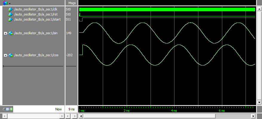
# Simulation result |
Simulations made in ModelSim. |
|
 |
|
# FPGA test |
Below is the oscillator frequency test video. A clock frequency of 48 kHz was used, so the oscillator generates a wave of approximately `48 kHz/100=480 Hz`. The video shows that a 475 Hz frequency wave was generated, very close to what was expected (this small difference is due to small numerical precision errors in the design of the IIR filter coefficients). |
|
[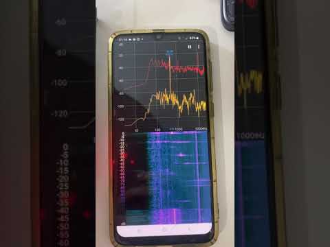](https://www.youtube.com/watch?v=TAZPnaK2IME) |
|
# Synthesis result |
|
Analysis and synthesis result (from Quartus Prime Lite Edition 18.1.0): |
|
| Family / Device | MAX 10 / 10M50DAF484C6GES| |
|------------------------------------|--------------| |
| Total logic elements | 97 | |
| Total registers | 34 | |
| Total pins | 35 | |
| Total virtual pins | 0 | |
| Total memory bits | 0 | |
| Embedded Multiplier 9-bit elements | 0 | |
| Total PLLs | 0 | |
|
# License |
|
MIT License |
|
Copyright (c) 2021 Davi C. M. de Almeida |