
URL
https://opencores.org/ocsvn/neorv32/neorv32/trunk
Subversion Repositories neorv32
Compare Revisions
- This comparison shows the changes necessary to convert path
/neorv32/trunk
- from Rev 68 to Rev 69
- ↔ Reverse comparison
Rev 68 → Rev 69
/docs/datasheet/cpu.adoc
252,36 → 252,29
This list shows the currently identified issues regarding full RISC-V-compatibility. More specific information |
can be found in section <<_instruction_sets_and_extensions>>. |
|
.Hardwired R/W CSRs |
.Read-Only "Read-Write" CSRs |
[IMPORTANT] |
The `misa`, `mip` and `mtval` CSRs in the NEORV32 are _read-only_. |
Any write access to it (in machine mode) to them are ignored and will _not_ cause any exceptions or side-effects. |
Pending interrupt can only be cleared by acknowledging the interrupt-causing device. However, pending interrupts |
can still be ignored by clearing the according `mie` register bits. |
The `misa` and `mtval` CSRs in the NEORV32 are _read-only_. |
Any machine-mode write access to them is ignored and will _not_ cause any exceptions or side-effects to maintain |
RISC-V compatibility. |
|
.Physical memory protection |
.Physical Memory Protection |
[IMPORTANT] |
The physical memory protection (see section <<_machine_physical_memory_protection>>) |
only supports the modes _OFF_ and _NAPOT_ yet and a minimal granularity of 8 bytes per region. |
|
.Atomic memory operations |
.Atomic Memory Operations |
[IMPORTANT] |
The `A` CPU extension only implements the `lr.w` and `sc.w` instructions yet. |
However, these instructions are sufficient to emulate all further atomic memory operations. |
|
.Bit-manipulation operations |
.Bit-Manipulation ISA Extension |
[IMPORTANT] |
The NEORV32 `B` extension only implements the _basic bit-manipulation instructions_ (`Zbb`) subset |
and the _address generation instructions_ (`Zba`) subset yet. |
|
.Instruction Misalignment |
[NOTE] |
This is not a real RISC-V incompatibility, but something that might not be clear when studying the RISC-V privileged |
architecture specifications: for 32-bit only instructions (no `C` extension) the misaligned instruction exception |
is raised if bit 1 of the access address is set (i.e. not on 32-bit boundary). If the `C` extension is implemented |
there will be no misaligned instruction exceptions _at all_. |
In both cases bit 0 of the program counter and all related registers is hardwired to zero. |
|
|
<<< |
// #################################################################################################################### |
:sectnums: |
300,6 → 293,7
| `clk_i` | 1 | in | global clock line, all registers triggering on rising edge |
| `rstn_i` | 1 | in | global reset, low-active |
| `sleep_o` | 1 | out | CPU is in sleep mode when set |
| `debug_o` | 1 | out | CPU is in debug mode when set |
4+^| **Instruction Bus Interface (<<_bus_interface>>)** |
| `i_bus_addr_o` | 32 | out | destination address |
| `i_bus_rdata_i` | 32 | in | read data |
561,7 → 555,7
|
The most important points of the NEORV32-specific extensions are: |
* The CPU provides 16 _fast interrupt_ interrupts (`FIRQ)`, which are controlled via custom bits in the `mie` |
and `mip` CSR. This extension is mapped to _reserved_ CSR bits, that are available for custom use (according to the |
and `mip` CSR. This extension is mapped to CSR bits, that are available for custom use (according to the |
RISC-V specs). Also, custom trap codes for `mcause` are implemented. |
* All undefined/unimplemented/malformed/illegal instructions do raise an illegal instruction exception (see <<_full_virtualization>>). |
|
780,8 → 774,8
| Memory access | `I/E` | `lb` `lh` `lw` `lbu` `lhu` `sb` `sh` `sw` | 4 + ML |
| Memory access | `C` | `c.lw` `c.sw` `c.lwsp` `c.swsp` | 4 + ML |
| Memory access | `A` | `lr.w` `sc.w` | 4 + ML |
| Multiplication | `M` | `mul` `mulh` `mulhsu` `mulhu` | 2+31+3; FAST_MULfootnote:[DSP-based multiplication; enabled via `FAST_MUL_EN`.]: 5 |
| Division | `M` | `div` `divu` `rem` `remu` | 22+32+4 |
| Multiplication | `M` | `mul` `mulh` `mulhsu` `mulhu` | 2+32+2; FAST_MULfootnote:[DSP-based multiplication; enabled via `FAST_MUL_EN`.]: 4 |
| Division | `M` | `div` `divu` `rem` `remu` | 2+32+2 |
| CSR access | `Zicsr` | `csrrw` `csrrs` `csrrc` `csrrwi` `csrrsi` `csrrci` | 4 |
| System | `I/E`+`Zicsr` | `ecall` `ebreak` | 4 |
| System | `I/E` | `fence` | 3 |
836,11 → 830,17
is serviced first while the remaining ones stay _pending_. After completing the interrupt handler the interrupt with |
the second highest priority will get serviced and so on until no further interrupt are pending. |
|
.Interrupt Signal Requirements |
.Interrupt Signal Requirements - Standard RISC-V Interrupts |
[IMPORTANT] |
All interrupts request signals (including FIRQs) are **high-active**. A request has to stay at high-level (=asserted) |
All standard RISC-V interrupts request signals are **high-active**. A request has to stay at high-level (=asserted) |
until it is explicitly acknowledged by the CPU software (for example by writing to a specific memory-mapped register). |
|
.Interrupt Signal Requirements - Fast Interrupt Requests |
[IMPORTANT] |
The NEORV32-specific FIRQ request lines are triggered by a rising edge. Each request is buffered in the CPU control |
unit until the channel is either disabled (by clearing the according `mie` CSR bit) or the request is explicitly cleared (by setting |
the according `mip` CSR bit). |
|
.Instruction Atomicity |
[NOTE] |
All instructions execute as atomic operations - interrupts can only trigger between two instructions. |
868,10 → 868,31
|
<<< |
// #################################################################################################################### |
:sectnums!: |
===== NEORV32 Trap Listing |
:sectnums: |
==== NEORV32 Trap Listing |
|
.NEORV32 trap listing |
The following table shows all traps that are currently supported by the NEORV32 CPU. It also shows the prioritization |
and the CSR side-effects. A more detailed description of the actual trap triggering events is provided in a further table. |
|
[NOTE] |
_Asynchronous exceptions_ (= interrupts) set the MSB of `mcause` while _synchronous exception_ (= "software exception") |
clear the MSB. |
|
**Table Annotations** |
|
The "Prio." column shows the priority of each trap. The highest priority is 1. The "`mcause`" column shows the |
cause ID of the according trap that is written to `mcause` CSR. The "[RISC-V]" columns show the interrupt/exception code value from the |
official RISC-V privileged architecture manual. The "[C]" names are defined by the NEORV32 core library (`sw/lib/include/neorv32.h`) and can |
be used in plain C code. The "`mepc`" and "`mtval`" columns show the value written to |
`mepc` and `mtval` CSRs when a trap is triggered: |
|
* _I-PC_ - address of interrupted instruction (instruction has not been execute/completed yet) |
* _B-ADR_- bad memory access address that cause the trap |
* _PC_ - address of instruction that caused the trap |
* _0_ - zero |
* _Inst_ - the faulting instruction itself |
|
.NEORV32 Trap Listing |
[cols="3,6,5,14,11,4,4"] |
[options="header",grid="rows"] |
|======================= |
881,7 → 902,7
| 3 | `0x00000002` | 0.2 | _TRAP_CODE_I_ILLEGAL_ | illegal instruction | _PC_ | _Inst_ |
| 4 | `0x0000000B` | 0.11 | _TRAP_CODE_MENV_CALL_ | environment call from M-mode (`ecall` in machine-mode) | _PC_ | _PC_ |
| 5 | `0x00000008` | 0.8 | _TRAP_CODE_UENV_CALL_ | environment call from U-mode (`ecall` in user-mode) | _PC_ | _PC_ |
| 6 | `0x00000003` | 0.3 | _TRAP_CODE_BREAKPOINT_ | breakpoint (EBREAK) | _PC_ | _PC_ |
| 6 | `0x00000003` | 0.3 | _TRAP_CODE_BREAKPOINT_ | breakpoint (`ebreak`) | _PC_ | _PC_ |
| 7 | `0x00000006` | 0.6 | _TRAP_CODE_S_MISALIGNED_ | store address misaligned | _B-ADR_ | _B-ADR_ |
| 8 | `0x00000004` | 0.4 | _TRAP_CODE_L_MISALIGNED_ | load address misaligned | _B-ADR_ | _B-ADR_ |
| 9 | `0x00000007` | 0.7 | _TRAP_CODE_S_ACCESS_ | store access fault | _B-ADR_ | _B-ADR_ |
907,20 → 928,36
| 29 | `0x80000007` | 1.7 | _TRAP_CODE_MTI_ | machine timer interrupt | _I-PC_ | _0_ |
|======================= |
|
**Notes** |
|
The "Prio." column shows the priority of each trap. The highest priority is 1. The "`mcause`" column shows the |
cause ID of the according trap that is written to `mcause` CSR. The "[RISC-V]" columns show the interrupt/exception code value from the |
official RISC-V privileged architecture manual. The "[C]" names are defined by the NEORV32 core library (`sw/lib/include/neorv32.h`) and can |
be used in plain C code. The "`mepc`" and "`mtval`" columns show the value written to |
`mepc` and `mtval` CSRs when a trap is triggered: |
The following table provides a summarized description of the actual events for triggering a specific trap. |
|
* _I-PC_ - address of interrupted instruction (instruction has not been execute/completed yet) |
* _B-ADR_- bad memory access address that cause the trap |
* _PC_ - address of instruction that caused the trap |
* _0_ - zero |
* _Inst_ - the faulting instruction itself |
.NEORV32 Trap Description |
[cols="<3,<7"] |
[options="header",grid="rows"] |
|======================= |
| Trap ID | Triggered when ... |
| _TRAP_CODE_I_MISALIGNED_ | fetching an 32-bit instruction word that is not 32-bit-aligned (_see note below!_) |
| _TRAP_CODE_I_ACCESS_ | bus timeout or bus error during instruction word fetch |
| _TRAP_CODE_I_ILLEGAL_ | trying to execute an invalid instruction word (malformed or not supported) or on a privilege violation |
| _TRAP_CODE_MENV_CALL_ | executing `ecall` instruction in machine-mode |
| _TRAP_CODE_UENV_CALL_ | executing `ecall` instruction in user-mode |
| _TRAP_CODE_BREAKPOINT_ | executing `ebreak` instruction (or triggered by on-chip debugger) |
| _TRAP_CODE_S_MISALIGNED_ | storing data to an address that is not naturally aligned to the data size (byte, half, word) being stored |
| _TRAP_CODE_L_MISALIGNED_ | loading data from an address that is not naturally aligned to the data size (byte, half, word) being loaded |
| _TRAP_CODE_S_ACCESS_ | bus timeout or bus error during load data operation |
| _TRAP_CODE_L_ACCESS_ | bus timeout or bus error during store data operation |
| _TRAP_CODE_FIRQ_0_ ... _TRAP_CODE_FIRQ_15_| caused by interrupt-condition of processor-internal modules, see <<_neorv32_specific_fast_interrupt_requests>> |
| _TRAP_CODE_MEI_ | user-defined processor-external source (via dedicated top-entity signal) |
| _TRAP_CODE_MSI_ | user-defined processor-external source (via dedicated top-entity signal) |
| _TRAP_CODE_MTI_ | processor-internal machine timer overflow OR user-defined processor-external source (via dedicated top-entity signal) |
|======================= |
|
.Instruction Address Misaligned Exception |
[NOTE] |
For 32-bit-only instructions (= no `C` extension) the misaligned instruction exception |
is raised if bit 1 of the fetch address is set (i.e. not on a 32-bit boundary). If the `C` extension is implemented |
there will never be a misaligned instruction exception _at all_. |
In both cases bit 0 of the program counter (and all related registers) is hardwired to zero. |
|
|
<<< |
/docs/datasheet/cpu_csr.adoc
60,7 → 60,7
* `C`: _constrained_ - have a constrained compatibility, not all specified bits are implemented |
|
.NEORV32 Control and Status Registers (CSRs) |
[cols="<4,<7,<10,^3,<11,^3"] |
[cols="<6,<11,<16,^3,<25,^3"] |
[options="header"] |
|======================= |
| Address | Name [ASM] | Name [C] | R/W | Function | Note |
82,8 → 82,8
| 0x340 | <<_mscratch>> | _CSR_MSCRATCH_ | r/w | Machine scratch register | |
| 0x341 | <<_mepc>> | _CSR_MEPC_ | r/w | Machine exception program counter | |
| 0x342 | <<_mcause>> | _CSR_MCAUSE_ | r/w | Machine trap cause | `X` |
| 0x343 | <<_mtval>> | _CSR_MTVAL_ | r/- | Machine bad address or instruction | `XR` |
| 0x344 | <<_mip>> | _CSR_MIP_ | r/- | Machine interrupt pending register | `XR` |
| 0x343 | <<_mtval>> | _CSR_MTVAL_ | r/- | Machine bad address or instruction | `R` |
| 0x344 | <<_mip>> | _CSR_MIP_ | r/w | Machine interrupt pending register | `X` |
6+^| **<<_machine_physical_memory_protection_csrs>>** |
| 0x3a0 .. 0x3af | <<_pmpcfg, `pmpcfg0`>> .. <<_pmpcfg, `pmpcfg15`>> | _CSR_PMPCFG0_ .. _CSR_PMPCFG15_ | r/w | Physical memory protection config. for region 0..63 | `C` |
| 0x3b0 .. 0x3ef | <<_pmpaddr, `pmpaddr0`>> .. <<_pmpaddr, `pmpaddr63`>> | _CSR_PMPADDR0_ .. _CSR_PMPADDR63_ | r/w | Physical memory protection addr. register region 0..63 | |
446,9 → 446,10
| 0x344 | **Machine interrupt Pending** | `mip` |
3+| Reset value: _0x00000000_ |
3+| The `mip` CSR is compatible to the RISC-V specifications and also provides custom extensions. It shows currently _pending_ interrupts. |
Since this register is read-only, pending interrupts of processor-internal modules can only be cleared by acknowledging the interrupt-causing |
device. However, pending interrupts can be ignored by clearing the according <<_mie>> register bits. |
The following CSR bits are implemented (all remaining bits are always zero and are read-only). |
The bits for the standard RISC-V interrupts are read-only. Hence, these interrupts cannot be cleared using the `mip` register and must |
be cleared/acknowledged within the according interrupt-generating device. |
The upper 16 bits represent the status of the CPU's fast interrupt request lines (FIRQ). Once triggered, these _have to be cleared_ again by setting |
the according `mip` bit in the interrupt handler routine to clear the current interrupt request. |
|====== |
|
.Machine interrupt pending register |
456,16 → 457,13
[options="header",grid="rows"] |
|======================= |
| Bit | Name [C] | R/W | Function |
| 31:16 | _CSR_MIP_FIRQ15P_ : _CSR_MIP_FIRQ0P_ | r/- | fast interrupt channel 15..0 pending |
| 11 | _CSR_MIP_MEIP_ | r/- | machine _external_ interrupt pending |
| 7 | _CSR_MIP_MTIP_ | r/- | machine _timer_ interrupt pending |
| 3 | _CSR_MIP_MSIP_ | r/- | machine _software_ interrupt pending |
| 31:16 | _CSR_MIP_FIRQ15P_ : _CSR_MIP_FIRQ0P_ | r/w | fast interrupt channel 15..0 pending; cleared request by writing 1 |
| 11 | _CSR_MIP_MEIP_ | r/- | machine _external_ interrupt pending; _cleared by user-defined mechanism_ |
| 7 | _CSR_MIP_MTIP_ | r/- | machine _timer_ interrupt pending; cleared by incrementing MTIME's time compare register |
| 3 | _CSR_MIP_MSIP_ | r/- | machine _software_ interrupt pending; _cleared by user-defined mechanism_ |
|======================= |
|
[IMPORTAN] |
The NEORV32 `mip` CSR is read-only. However, a write access will _NOT_ raise an illegal instruction exception. |
|
|
<<< |
// #################################################################################################################### |
:sectnums: |
/docs/datasheet/overview.adoc
181,15 → 181,16
├common - Linker script, crt0.S start-up code and central makefile |
├example - Various example programs |
│└... |
├lib - Processor core library |
│├include - Header files (*.h) |
│└source - Source files (*.c) |
├image_gen - Helper program to generate NEORV32 executables |
├isa-test |
│├riscv-arch-test - RISC-V spec. compatibility test framework (submodule) |
│└port-neorv32 - Port files for the official RISC-V architecture tests |
├ocd_firmware - Source code for on-chip debugger's "park loop" |
├openocd - OpenOCD on-chip debugger configuration files |
├image_gen - Helper program to generate NEORV32 executables |
└lib - Processor core library |
├include - Header files (*.h) |
└source - Source files (*.c) |
└svd - Processor system view description file (CMSIS-SVD) |
................................... |
|
|
277,6 → 278,8
|======================= |
| Hardware version: | `1.5.7.10` |
| Top entity: | `rtl/core/neorv32_cpu.vhd` |
| FPGA: | Intel Cyclone IV E `EP4CE22F17C6` |
| Toolchain: | Quartus Prime 20.1.0 |
|======================= |
|
[cols="<5,>1,>1,>1,>1,>1"] |
294,9 → 297,6
| `rv32imacu_Zicsr_Zicntr_Zifencei_Zfinx_DebugMode` | 3974 | 1815 | 1024 | 7 | 116 MHz |
|======================= |
|
[NOTE] |
No HPM counters and no PMP regions were implemented for generating these results. |
|
[TIP] |
The CPU provides further options to reduce the area footprint (for example by constraining the CPU-internal |
counter sizes) or to increase performance (for example by using a barrel-shifter; at cost of extra hardware). |
312,6 → 312,8
|======================= |
| Hardware version: | `1.5.7.15` |
| Top entity: | `rtl/core/neorv32_top.vhd` |
| FPGA: | Intel Cyclone IV E `EP4CE22F17C6` |
| Toolchain: | Quartus Prime 20.1.0 |
|======================= |
|
.Hardware utilization by the processor modules (mandatory core modules in **bold**) |
/docs/datasheet/soc.adoc
1057,9 → 1057,8
|
.Trigger type |
[IMPORTANT] |
The fast interrupt request channel trigger on **high-level** and have to stay asserted until explicitly acknowledged |
by the software (for example by writing to a specific memory-mapped register). Hence, pending interrupts remain pending |
as long as the interrupt-causing device's state fulfills it's interrupt condition(s). |
The fast interrupt request channels become pending after being triggering by **a rising edge**. A pending FIRQ has to |
be explicitly cleared by setting the according `mip` CSR bit. |
|
|
:sectnums: |
1117,9 → 1116,8
|
.Trigger type |
[IMPORTANT] |
The fast interrupt request channel trigger on **high-level** and have to stay asserted until explicitly acknowledged |
by the software (for example by writing to a specific memory-mapped register). Hence, pending interrupts remain pending |
as long as the interrupt-causing device's state fulfills it's interrupt condition(s). |
The fast interrupt request channels become pending after being triggering by **a rising edge**. A pending FIRQ has to |
be explicitly cleared by setting the according `mip` CSR bit. |
|
|
|
1424,6 → 1422,9
register and register bit accesses. |
|
[TIP] |
A CMSIS-SVD-compatible **System View Description (SVD)** file including all peripherals is available in `sw/svd`. |
|
[TIP] |
Most of the IO devices do not have a hardware reset. Instead, the devices are reset via software by |
writing zero to the unit's control register. A general software-based reset of all devices is done by the |
application start-up code `crt0.S`. |
/docs/datasheet/soc_cfs.adoc
55,9 → 55,9
|
**CFS Interrupt** |
|
The CFS provides a single high-level-triggered interrupt request signal mapped to the CPU's fast interrupt channel 1. |
Once set, the interrupt has to stay asserted until explicitly acknowledged by the software (for example by |
writing to a specific CFS register). See section <<_processor_interrupts>> for more information. |
The CFS provides a single rising-edge-triggered interrupt request signal mapped to the CPU's fast interrupt channel 1. |
Once triggered, the interrupt becomes pending (if enabled in the `mis` CSR) and has to be explicitly cleared again by setting |
the according `mip` CSR bit. See section <<_processor_interrupts>> for more information. |
|
|
**CFS Configuration Generic** |
/docs/datasheet/soc_gptmr.adoc
46,10 → 46,8
|
**Timer Interrupt** |
|
The timer interrupt gets pending when the timer is enabled and `COUNT` matches `THRES`. The interrupt |
request is indicated via the _GPTMR_CTRL_ALARM_ control register bit. This bit as well as the actual |
interrupt keeps pending until the bit is explicitly cleared by application software or if the |
timer is disabled. |
The timer interrupt is triggered when the timer is enabled and `COUNT` matches `THRES`. The interrupt |
remains pending until explicitly cleared by writing the according `mip` CSR bit. |
|
|
.GPTMR register map (`struct NEORV32_GPTMR`) |
57,12 → 55,11
[options="header",grid="all"] |
|======================= |
| Address | Name [C] | Bit(s), Name [C] | R/W | Function |
.6+<| `0xffffff60` .6+<| `NEORV32_GPTMR.CTRL` <|`0` _GPTMR_CTRL_EN_ ^| r/w <| Timer enable flag |
.5+<| `0xffffff60` .5+<| `NEORV32_GPTMR.CTRL` <|`0` _GPTMR_CTRL_EN_ ^| r/w <| Timer enable flag |
<|`1` _GPTMR_CTRL_PRSC0_ ^| r/w .3+| 3-bit clock prescaler select |
<|`2` _GPTMR_CTRL_PRSC1_ ^| r/w |
<|`3` _GPTMR_CTRL_PRSC2_ ^| r/w |
<|`4` _GPTMR_CTRL_MODE_ ^| r/w <| Counter mode: `0`=single-shot, `1`=continuous |
<|`5` _GPTMR_CTRL_ALARM_ ^| r/c <| Pending interrupt/alarm, cleared by setting bit to zero |
| `0xffffff64` | `NEORV32_GPTMR.THRES` |`31:0` | r/w | Threshold value register |
| `0xffffff68` | `NEORV32_GPTMR.COUNT` |`31:0` | r/w | Counter register |
|======================= |
/docs/datasheet/soc_neoled.adoc
173,14 → 173,11
In this case software can write up to _IO_NEOLED_TX_FIFO_/2 new data words to `DATA` without checking the FIFO |
status flags. If _NEOLED_CTRL_IRQ_CONF_ is set, an interrupt is generated whenever the TX FIFO _becomes_ empty. |
|
A pending interrupt request is cleared is cleared by any of the following operations: |
* write access to `NEORV32_NEOLED.DATA` (for example to send more LED data) |
* write access to `NEORV32_NEOLED.CTRL` |
* disabling the NEOLED module |
One the NEOLED interrupt has been triggered and became pending, it has to explicitly cleared again by setting the |
according `mip` CSR bit. |
|
[NOTE] |
The _NEOLED_CTRL_IRQ_CONF_ is hardwired to one if _IO_NEOLED_TX_FIFO_ = 1 (-> IRQ if FIFO is empty). |
|
If the FIFO is configured to contain only a single entry (_IO_NEOLED_TX_FIFO_ = 1) the interrupt |
will become pending if the FIFO (which is just a single register providing simple _double-buffering_) is empty. |
|
/docs/datasheet/soc_slink.adoc
137,13 → 137,16
request if it's interrupt enable flag _SLINK_IRQ_TX_EN_ is set. |
|
The **RX link's** _SLINK_IRQ_RX_MODE_ flags define the FIFO fill-level condition for raising an RX interrupt request: |
* If a link's interrupt mode flag is `1` an IRQ is generated when the link's FIFO _becomes_ not empty ("RX data available"). |
* If a link's interrupt mode flag is `0` an IRQ is generated when the link's FIFO _becomes_ at least half-full ("time to get data from RX FIFO to prevent overflow"). |
* If a link's interrupt mode flag is `0` an IRQ is generated when the link's FIFO _becomes_ not empty ("RX data available"). |
* If a link's interrupt mode flag is `1` an IRQ is generated when the link's FIFO _becomes_ at least half-full ("time to get data from RX FIFO to prevent overflow"). |
|
The **TX link's** _SLINK_IRQ_TX_MODE_ flags define the FIFO fill-level condition for raising an TX interrupt request: |
* If a link's interrupt mode flag is `1` an IRQ is generated when the link's FIFO _becomes_ not full ("space left in FIFO for new TX data"). |
* If a link's interrupt mode flag is `0` an IRQ is generated when the link's FIFO _becomes_ less than half-full ("SW can send _SLINK_TX_FIFO_/2 data words without checking any flags"). |
* If a link's interrupt mode flag is `0` an IRQ is generated when the link's FIFO _becomes_ not full ("space left in FIFO for new TX data"). |
* If a link's interrupt mode flag is `1` an IRQ is generated when the link's FIFO _becomes_ less than half-full ("SW can send _SLINK_TX_FIFO_/2 data words without checking any flags"). |
|
Once the SLINK's RX or TX interrupt has become pending, it has to be explicitly cleared again by setting the according |
`mip` CSR bit. |
|
[IMPORTANT] |
The interrupt configuration register `NEORV32_SLINK.IRQ` should we written _before_ the SLINK |
module is actually enabled. |
152,21 → 155,7
If _SLINK_RX_FIFO_ is 1 all _SLINK_IRQ_RX_MODE_ bits are hardwired to one. |
If _SLINK_TX_FIFO_ is 1 all _SLINK_IRQ_TX_MODE_ bits are hardwired to one. |
|
A **pending RX interrupt** request is cleared by any of the following operations: |
* read access to any `NEORV32_SLINK.DATA` (for example to read incoming data) |
* write access to `NEORV32_SLINK.CTRL` |
* disabling the SLINK module |
|
A **pending TX interrupt** request is cleared by any of the following operations: |
* write access any `NEORV32_SLINK.DATA` (for example to send more data) |
* write access to `NEORV32_SLINK.CTRL` |
* disabling the SLINK module |
|
[TIP] |
A dummy write to to the control register (i.e. `NEORV32_SLINK.DATA = NEORV32_SLINK.DATA`) |
can be executed to acknowledge any interrupt. |
|
|
.SLINK register map (`struct NEORV32_SLINK`) |
[cols="^4,<5,^2,^2,<14"] |
[options="header",grid="all"] |
/docs/datasheet/soc_spi.adoc
108,17 → 108,10
**SPI Interrupt** |
|
The SPI module provides a single interrupt to signal "transmission done" to the CPU. Whenever the SPI |
module completes the current transfer operation, the interrupt request is set. A pending interrupt request |
is cleared by any of the following operations: |
* read or write access to `NEORV32_SPI.DATA` (for example to trigger a new transmission) |
* write access to `NEORV32_SPI.CTRL` |
* disabling the SPI module |
module completes the current transfer operation, the interrupt is triggered and has to be explicitly cleared again |
by setting the according `mip` CSR bit. |
|
[TIP] |
A dummy read from `NEORV32_SPI.DATA` can be executed to acknowledge the interrupt without affecting data |
or the state of the SPI module. |
|
|
.SPI register map (`struct NEORV32_SPI`) |
[cols="<2,<2,<4,^1,<7"] |
[options="header",grid="all"] |
/docs/datasheet/soc_sysinfo.adoc
71,6 → 71,7
| `3` | _SYSINFO_SOC_MEM_INT_DMEM_ | set if the processor-internal IMEM is implemented (via top's <<_mem_int_imem_en>> generic) |
| `4` | _SYSINFO_SOC_MEM_EXT_ENDIAN_ | set if external bus interface uses BIG-endian byte-order (via top's <<_mem_ext_big_endian>> generic) |
| `5` | _SYSINFO_SOC_ICACHE_ | set if processor-internal instruction cache is implemented (via top's <<_icache_en>> generic) |
| `13` | _SYSINFO_SOC_IS_SIM_ | set if processor is being **simulated** (⚠️ not guaranteed) |
| `14` | _SYSINFO_SOC_OCD_ | set if on-chip debugger implemented (via top's <<_on_chip_debugger_en>> generic) |
| `15` | _SYSINFO_SOC_HW_RESET_ | set if a dedicated hardware reset of all core registers is implemented (via package's `dedicated_reset_c` constant) |
| `16` | _SYSINFO_SOC_IO_GPIO_ | set if the GPIO is implemented (via top's <<_io_gpio_en>> generic) |
/docs/datasheet/soc_twi.adoc
74,17 → 74,10
|
The SPI module provides a single interrupt to signal "operation done" to the CPU. Whenever the TWI |
module completes the current operation (generate stop condition, generate start conditions or transfer byte), |
the interrupt request is set. A pending interrupt request is cleared is cleared by any of |
the following operations: |
* read or write access to `NEORV32_TWI.DATA` (for example to trigger a new transmission) |
* write access to `NEORV32_TWI.CTRL` |
* disabling the TWI module |
the interrupt is triggered. Once triggered, the interrupt has to be explicitly cleared again by setting the according |
`mip` CSR bit. |
|
[TIP] |
A dummy read from `NEORV32_TWI.DATA` can be executed to acknowledge the interrupt without affecting data |
or the state of the TWI module. |
|
|
.TWI register map (`struct NEORV32_TWI`) |
[cols="<2,<2,<4,^1,<7"] |
[options="header",grid="all"] |
/docs/datasheet/soc_uart.adoc
127,21 → 127,10
in the TX FIFO _becomes_ free (-> _UART_CTRL_TX_FULL_ clears). If _UART_CTRL_TX_IRQ_ is `1` the TX interrupt goes pending |
when the RX FIFO _becomes_ less than half-full (-> _UART_CTRL_TX_HALF_ clears). |
|
A **pending RX interrupt** request is cleared by any of the following operations: |
* read access to `NEORV32_UART0.DATA` (for example to read incoming data) |
* write access to `NEORV32_UART0.CTRL` |
* disabling the UART module |
Once the RX or TX interrupt has become pending, it has to be explicitly cleared again by setting the |
according `mip` CSR bit. |
|
A **pending TX interrupt** request is cleared by any of the following operations: |
* write access to `NEORV32_UART0.DATA` (for example to send more data) |
* write access to `NEORV32_UART0.CTRL` |
* disabling the UART module |
|
[TIP] |
A dummy write to to the control register (i.e. `NEORV32_UART0.DATA = NEORV32_UART0.DATA`) |
can be executed to acknowledge any interrupt. |
|
|
**Simulation Mode** |
|
The default UART0 operation will transmit any data written to the `DATA` register via the serial TX line at |
/docs/datasheet/soc_wdt.adoc
13,15 → 13,17
| CPU interrupts: | fast IRQ channel 0 | watchdog timer overflow (see <<_processor_interrupts>>) |
|======================= |
|
|
**Theory of Operation** |
|
The watchdog (WDT) provides a last resort for safety-critical applications. The WDT has an internal 20-bit |
wide counter that needs to be reset every now and then by the user program. If the counter overflows, either |
a system reset or an interrupt is generated (depending on the configured operation mode). |
The _WDT_CTRL_HALF_ flag of the control register `CTRL` indicates that at least half of the maximum timeout |
value has been reached. |
|
Configuration of the watchdog is done by a single control register `CTRL`. The watchdog is enabled by |
setting the _WDT_CTRL_EN_ bit. The clock used to increment the internal counter is selected via the 3-bit |
_WDT_CTRL_CLK_SELx_ prescaler: |
The watchdog is enabled by setting the _WDT_CTRL_EN_ bit. The clock used to increment the internal counter |
is selected via the 3-bit _WDT_CTRL_CLK_SELx_ prescaler: |
|
[cols="^3,^3,>4"] |
[options="header",grid="rows"] |
44,7 → 46,7
any time by setting the _WDT_CTRL_FORCE_ bit. The watchdog is reset by setting the _WDT_CTRL_RESET_ bit. |
|
A watchdog interrupt can only occur if the watchdog is enabled and interrupt mode is enabled. |
A pending interrupt is cleared by either disabling the watchdog or by resetting the watchdog. |
A triggered interrupt has to be cleared again by setting the according `mip` CSR bit. |
|
The cause of the last action of the watchdog can be determined via the _WDT_CTRL_RCAUSE_ flag. If this flag is |
zero, the processor has been reset via the external reset signal. If this flag is set the last system reset was |
52,21 → 54,32
|
The Watchdog control register can be locked in order to protect the current configuration. The lock is |
activated by setting bit _WDT_CTRL_LOCK_. In the locked state any write access to the configuration flags is |
ignored (see table below, "accessible if locked"). Read accesses to the control register are not effected. The |
ignored (see table below, "writable if locked"). Read accesses to the control register are not effected. The |
lock can only be removed by a system reset (via external reset signal or via a watchdog reset action). |
|
.Watchdog Operation during Debugging |
[IMPORTANT] |
By default the watchdog pauses operation when the CPU enters debug mode and will resume normal operation after |
the CPU has left debug mode. This will prevent an unintended watchdog timeout (and a hardware reset if configured) |
during a debug session. However, the watchdog can be configured to keep operating even when the CPU is in debug |
mode by setting the control register's _WDT_CTRL_DBEN_ bit. If the CPU's debug mode is not implemented this flag |
is hardwired to zero. |
|
|
.WDT register map (`struct NEORV32_WDT`) |
[cols="<2,<2,<4,^1,^2,<4"] |
[cols="<2,<2,<4,^1,^1,^2,<4"] |
[options="header",grid="all"] |
|======================= |
| Address | Name [C] | Bit(s), Name [C] | R/W | Writable if locked | Function |
.9+<| `0xffffffbc` .9+<| `NEORV32_WDT.CTRL` <|`0` _WDT_CTRL_EN_ ^| r/w ^| no <| watchdog enable |
<|`1` _WDT_CTRL_CLK_SEL0_ ^| r/w ^| no .3+<| 3-bit clock prescaler select |
<|`2` _WDT_CTRL_CLK_SEL1_ ^| r/w ^| no |
<|`3` _WDT_CTRL_CLK_SEL2_ ^| r/w ^| no |
<|`4` _WDT_CTRL_MODE_ ^| r/w ^| no <| overflow action: `1`=reset, `0`=IRQ |
<|`5` _WDT_CTRL_RCAUSE_ ^| r/- ^| - <| cause of last system reset: `0`=caused by external reset signal, `1`=caused by watchdog |
<|`6` _WDT_CTRL_RESET_ ^| -/w ^| yes <| watchdog reset when set, auto-clears |
<|`7` _WDT_CTRL_FORCE_ ^| -/w ^| yes <| force configured watchdog action when set, auto-clears |
<|`8` _WDT_CTRL_LOCK_ ^| r/w ^| no <| lock access to configuration when set, clears only on system reset (via external reset signal OR watchdog reset action = reset) |
| Address | Name [C] | Bit(s), Name [C] | R/W | Reset value | Writable if locked | Function |
.11+<| `0xffffffbc` .11+<| `NEORV32_WDT.CTRL` <|`0` _WDT_CTRL_EN_ ^| r/w ^| `0` ^| no <| watchdog enable |
<|`1` _WDT_CTRL_CLK_SEL0_ ^| r/w ^| `0` ^| no .3+<| 3-bit clock prescaler select |
<|`2` _WDT_CTRL_CLK_SEL1_ ^| r/w ^| `0` ^| no |
<|`3` _WDT_CTRL_CLK_SEL2_ ^| r/w ^| `0` ^| no |
<|`4` _WDT_CTRL_MODE_ ^| r/w ^| `0` ^| no <| overflow action: `1`=reset, `0`=IRQ |
<|`5` _WDT_CTRL_RCAUSE_ ^| r/- ^| `0` ^| - <| cause of last system reset: `0`=caused by external reset signal, `1`=caused by watchdog |
<|`6` _WDT_CTRL_RESET_ ^| -/w ^| - ^| yes <| watchdog reset when set, auto-clears |
<|`7` _WDT_CTRL_FORCE_ ^| -/w ^| - ^| yes <| force configured watchdog action when set, auto-clears |
<|`8` _WDT_CTRL_LOCK_ ^| r/w ^| `0` ^| no <| lock access to configuration when set, clears only on system reset (via external reset signal OR watchdog reset action = reset) |
<|`9` _WDT_CTRL_DBEN_ ^| r/w ^| `0` ^| no <| allow WDT to continue operation even when in debug mode |
<|`10` _WDT_CTRL_HALF_ ^| r/- ^| `0` ^| - <| set if at least half of the max. timeout counter value has been reached |
|======================= |
/docs/datasheet/soc_wishbone.adoc
28,28 → 28,32
| CPU interrupts: | none | |
|======================= |
|
The external memory interface uses the Wishbone interface protocol. The external interface port is available |
when the _MEM_EXT_EN_ generic is _true_. This interface can be used to attach external memories, custom |
hardware accelerators additional IO devices or all other kinds of IP blocks. All memory accesses from the |
CPU, that do not target the internal bootloader ROM, the internal IO region or the internal data/instruction |
memories (if implemented at all) are forwarded to the Wishbone gateway and thus to the external memory |
interface. |
|
The external memory interface provides a Wishbone b4-compatible on-chip bus interface. The bus interface is |
implemented when the _MEM_EXT_EN_ generic is _true_. This interface can be used to attach external memories, |
custom hardware accelerators, additional IO devices or all other kinds of IP blocks. |
|
The external interface is _not_ mapped to a _specific_ address space region. Instead, all CPU memory accesses that |
do not target a processor-internal module are delegated to the external memory interface. In summary, a CPU load/store |
access is delegated to the external bus interface if... |
|
. it does not target the internal instruction memory IMEM (if implemented at all) |
. **and** it does not target the internal data memory DMEM (if implemented at all) |
. **and** it does not target the internal bootloader ROM or any of the IO devices - regardless if one or more of these components are |
actually implemented or not. |
|
[TIP] |
When using the default processor setup, all access addresses between 0x00000000 and |
0xffff0000 (= beginning of processor-internal BOOT ROM) are delegated to the external memory |
/ bus interface if they are not targeting the (actually enabled/implemented) processor-internal |
instruction memory (IMEM) or the (actually enabled/implemented) processor-internal data memory |
(DMEM). See section <<_address_space>> for more information. |
See section <<_address_space>> for more information. |
|
|
**Wishbone Bus Protocol** |
|
The external memory interface either uses **standard** ("classic") Wishbone transactions (default) or |
**pipelined** Wishbone transactions. The transaction protocol is configured via the _MEM_EXT_PIPE_MODE_ generic: |
The external memory interface either uses the **standard** ("classic") Wishbone transaction protocol (default) or |
**pipelined** Wishbone transaction protocol. The transaction protocol is configured via the _MEM_EXT_PIPE_MODE_ generic: |
|
When _MEM_EXT_PIPE_MODE_ is _false_, all bus control signals including _STB_ are active (and stable) until the |
When _MEM_EXT_PIPE_MODE_ is _false_, all bus control signals including _STB_ are active and remain stable until the |
transfer is acknowledged/terminated. If _MEM_EXT_PIPE_MODE_ is _true_, all bus control except _STB_ are active |
(and stable) until the transfer is acknowledged/terminated. In this case, _STB_ is active only during the very |
and remain until the transfer is acknowledged/terminated. In this case, _STB_ is asserted only during the very |
first bus clock cycle. |
|
.Exemplary Wishbone bus accesses using "classic" and "pipelined" protocol |
62,39 → 66,37
|======================= |
|
|
[TOP] |
[TIP] |
A detailed description of the implemented Wishbone bus protocol and the according interface signals |
can be found in the data sheet "Wishbone B4 - WISHBONE System-on-Chip (SoC) Interconnection |
Architecture for Portable IP Cores". A copy of this document can be found in the docs folder of this |
project. |
|
**Interface Latency** |
|
By default, the Wishbone gateway introduces two additional latency cycles: processor-outgoing ("TX") and |
processor-incoming ("RX") signals are fully registered. Thus, any access from the CPU to a processor-external devices |
via Wishbone requires 2 additional clock cycles (at least; depending on device's latency). |
**Bus Access** |
|
If the attached Wishbone network / peripheral already provides output registers or if the Wishbone network is not relevant |
for timing closure, the default buffering of incoming ("RX") data within the gateway can be disabled by implementing an |
"asynchronous" RX path. The configuration is done via the _MEM_EXT_ASYNC_RX_ generic. |
The NEORV32 Wishbone gateway does not support burst transfer yet, so there is always just one transfer in progress. |
Hence, the Wishbone `STALL` signal is not implemented. An accessed Wishbone device does not have to respond immediately to a bus |
request by sending an ACK. instead, there is a _time window_ where the device has to acknowledge the transfer. This time window |
id configured by the _MEM_EXT_TIMEOUT_ top generic that defines the maximum time (in clock cycles) a bus access can be pending |
before it is automatically terminated. If _MEM_EXT_TIMEOUT_ is set to zero, the timeout disabled an a bus access can take an |
arbitrary number of cycles to complete. |
|
**Bus Access Timeout** |
|
The Wishbone bus interface provides an option to configure a bus access timeout counter. The _MEM_EXT_TIMEOUT_ |
top generic is used to specify the _maximum_ time (in clock cycles) a bus access can be pending before it is automatically |
terminated. If _MEM_EXT_TIMEOUT_ is set to zero, the timeout disabled an a bus access can take an arbitrary number of cycles to complete. |
|
When _MEM_EXT_TIMEOUT_ is greater than zero, the WIshbone adapter starts an internal countdown whenever the CPU |
When _MEM_EXT_TIMEOUT_ is greater than zero, the Wishbone gateway starts an internal countdown whenever the CPU |
accesses a memory address via the external memory interface. If the accessed memory / device does not acknowledge (via `wb_ack_i`) |
or terminate (via `wb_err_i`) the transfer within _MEM_EXT_TIMEOUT_ clock cycles, the bus access is automatically canceled |
(setting `wb_cyc_o` low again) and a load/store/instruction fetch bus access fault exception is raised. |
setting `wb_cyc_o` low again and a CPU load/store/instruction fetch bus access fault exception is raised. |
|
[TIP] |
This feature can be used as **safety guard** if the external memory system does not check for "address space holes". That means that addresses, which |
do not belong to a certain memory or device, do not permanently stall the processor due to an unacknowledged/unterminated bus access. If the external |
memory system can guarantee to access **any** bus access (even it targets an unimplemented address) the timeout feature should be disabled |
(_MEM_EXT_TIMEOUT_ = 0). |
[IMPORTANT] |
Setting _MEM_EXT_TIMEOUT_ to zero will permanently stall the CPU if the targeted Wishbone device never responds. Hence, |
_MEM_EXT_TIMEOUT_ should be always set to a value greater than zero. + |
+ |
This feature can be used as **safety guard** if the external memory system does not check for "address space holes". That means |
that accessing addresses, which do not belong to a certain memory or device, do not permanently stall the processor due to an |
unacknowledged/unterminated bus access. If the external memory system can guarantee to access **any** bus access |
(even it targets an unimplemented address) the timeout feature should be disabled (_MEM_EXT_TIMEOUT_ = 0). |
|
|
**Wishbone Tag** |
|
The 3-bit wishbone `wb_tag_o` signal provides additional information regarding the access type. This signal |
104,6 → 106,7
* `wb_tag_o(1)` always zero (indicating "secure access") |
* `wb_tag_o(2)` 1: instruction fetch access, 0: data access |
|
|
**Exclusive / Atomic Bus Access** |
|
If the atomic memory access CPU extension (via _CPU_EXTENSION_RISCV_A_) is enabled, the CPU can |
120,6 → 123,7
[TIP] |
See section <<_bus_interface>> for the CPU bus interface protocol. |
|
|
**Endianness** |
|
The NEORV32 CPU and the Processor setup are *little-endian* architectures. To allow direct connection |
130,6 → 134,18
Application software can check the Endianness configuration of the external bus interface via the |
SYSINFO module (see section <<_system_configuration_information_memory_sysinfo>> for more information). |
|
|
**Gateway Latency** |
|
By default, the Wishbone gateway introduces two additional latency cycles: processor-outgoing ("TX") and |
processor-incoming ("RX") signals are fully registered. Thus, any access from the CPU to a processor-external devices |
via Wishbone requires 2 additional clock cycles (at least; depending on device's latency). |
|
If the attached Wishbone network / peripheral already provides output registers or if the Wishbone network is not relevant |
for timing closure, the default buffering of incoming ("RX") data within the gateway can be disabled by implementing an |
"asynchronous" RX path. The configuration is done via the _MEM_EXT_ASYNC_RX_ generic. |
|
|
**AXI4-Lite Connectivity** |
|
The AXI4-Lite wrapper (`rtl/system_integration/neorv32_SystemTop_axi4lite.vhd`) provides a Wishbone-to- |
143,5 → 159,6
image::neorv32_axi_soc.png[] |
|
[WARNING] |
Using the auto-termination timeout feature (_MEM_EXT_TIMEOUT_ greater than zero) is **not AXI4 compliant** as the AXI protocol does not support canceling of |
bus transactions. Therefore, the NEORV32 top wrapper with AXI4-Lite interface (`rtl/system_integration/neorv32_SystemTop_axi4lite`) configures _MEM_EXT_TIMEOUT_ = 0 by default. |
Using the auto-termination timeout feature (_MEM_EXT_TIMEOUT_ greater than zero) is **not AXI4 compliant** as |
the AXI protocol does not support canceling of bus transactions. Therefore, the NEORV32 top wrapper with AXI4-Lite interface |
(`rtl/system_integration/neorv32_SystemTop_axi4lite`) configures _MEM_EXT_TIMEOUT_ = 0 by default. |
/docs/datasheet/soc_xirq.adoc
42,7 → 42,8
The CPU can use the ID from `SCR` to service IRQ according to their priority. To acknowledge the according |
interrupt the CPU can write `1 << SCR` to `IPR`. |
|
In order to clear a pending FIRQ interrupt from the external interrupt controller, the CPU has to write _any_ |
In order to clear a pending FIRQ interrupt from the external interrupt controller again, the according `mip` CSR bit has |
to be set. Additionally, the XIRQ interrupt has to be acknowledged by writing _any_ |
value to the interrupt source register `SRC`. |
|
[NOTE] |
/docs/datasheet/software.adoc
51,6 → 51,9
#include <neorv32.h> |
---- |
|
[TIP] |
A CMSIS-SVD-compatible **System View Description (SVD)** file including all peripherals is available in `sw/svd`. |
|
Together with the makefile, this will automatically include all the processor's header files located in |
`sw/lib/include` into your application. The actual source files of the core libraries are located in |
`sw/lib/source` and are automatically included into the source list of your software project. The following |
65,8 → 68,7
| `neorv32_cpu.c` | `neorv32_cpu.h` | HW driver functions for the NEORV32 **CPU** |
| `neorv32_gpio.c` | `neorv32_gpio.h` | HW driver functions for the **GPIO** |
| `neorv32_gptmr.c` | `neorv32_gptmr.h` | HW driver functions for the **GPTRM** |
| - | `neorv32_intrinsics.h` | macros for custom intrinsics/instructions |
| - | `neorv32_legacy.h` | legacy back-compatibility layer |
| - | `neorv32_intrinsics.h` | macros for (custom) intrinsics/instructions |
| `neorv32_mtime.c` | `neorv32_mtime.h` | HW driver functions for the **MTIME** |
| `neorv32_neoled.c` | `neorv32_neoled.h` | HW driver functions for the **NEOLED** |
| `neorv32_pwm.c` | `neorv32_pwm.h` | HW driver functions for the **PWM** |
119,23 → 121,34
[source,makefile] |
---- |
$ make |
<<< NEORV32 Application Makefile >>> |
<<< NEORV32 SW Application Makefile >>> |
Make sure to add the bin folder of RISC-V GCC to your PATH variable. |
Targets: |
help - show this text |
check - check toolchain |
info - show makefile/toolchain configuration |
exe - compile and generate <neorv32_exe.bin> executable for upload via bootloader |
hex - compile and generate <neorv32_exe.hex> executable raw file |
image - compile and generate VHDL IMEM boot image (for application) in local folder |
install - compile, generate and install VHDL IMEM boot image (for application) |
sim - in-console simulation using default/simple testbench and GHDL |
all - exe + hex + install |
elf_info - show ELF layout info |
clean - clean up project |
clean_all - clean up project, core libraries and image generator |
bl_image - compile and generate VHDL BOOTROM boot image (for bootloader only!) in local folder |
bootloader - compile, generate and install VHDL BOOTROM boot image (for bootloader only!) |
|
== Targets == |
help - show this text |
check - check toolchain |
info - show makefile/toolchain configuration |
exe - compile and generate <neorv32_exe.bin> executable for upload via bootloader |
hex - compile and generate <neorv32_exe.hex> executable raw file |
image - compile and generate VHDL IMEM boot image (for application) in local folder |
install - compile, generate and install VHDL IMEM boot image (for application) |
sim - in-console simulation using default/simple testbench and GHDL |
all - exe + hex + install |
elf_info - show ELF layout info |
clean - clean up project |
clean_all - clean up project, core libraries and image generator |
bl_image - compile and generate VHDL BOOTROM boot image (for bootloader only!) in local folder |
bootloader - compile, generate and install VHDL BOOTROM boot image (for bootloader only!) |
|
== Variables == |
USER_FLAGS - Custom toolchain flags [append only], default "" |
EFFORT - Optimization level, default "-Os" |
MARCH - Machine architecture, default "rv32i" |
MABI - Machine binary interface, default "ilp32" |
APP_INC - C include folder(s) [append only], default "-I ." |
ASM_INC - ASM include folder(s) [append only], default "-I ." |
RISCV_PREFIX - Toolchain prefix, default "riscv32-unknown-elf-" |
NEORV32_HOME - NEORV32 home folder, default "../../.." |
---- |
|
|
506,8 → 519,8
* `h`: Show the help text (again) |
* `r`: Restart the bootloader and the auto-boot sequence |
* `u`: Upload new program executable (`neorv32_exe.bin`) via UART into the instruction memory |
* `s`: Store executable to SPI flash at `spi_csn_o(0)` |
* `l`: Load executable from SPI flash at `spi_csn_o(0)` |
* `s`: Store executable to SPI flash at `spi_csn_o(0)` (little-endian byte order) |
* `l`: Load executable from SPI flash at `spi_csn_o(0)` (little-endian byte order) |
* `e`: Start the application, which is currently stored in the instruction memory (IMEM) |
|
A new executable can be uploaded via UART by executing the `u` command. After that, the executable can be directly |
/docs/figures/license.md
2,6 → 2,16
|
Figures are own work if not otherwise stated. License: https://github.com/stnolting/neorv32/blob/master/LICENSE |
|
No copyright infringement intended. |
|
|
## `neopixel.png` |
|
source: Adafruit NeoPixel Überguide |
|
License: |
* ? |
|
## `SPI_timing_diagram2.wikimedia.png` |
|
source: https://en.wikipedia.org/wiki/File:SPI_timing_diagram2.svg |
8,4 → 18,25
|
License: |
* Creative Commons: https://en.wikipedia.org/wiki/Creative_Commons |
* Attribution-Share Alike 3.0 Unported: https://creativecommons.org/licenses/by-sa/3.0/deed.en |
* Attribution-Share Alike 3.0 Unported: https://creativecommons.org/licenses/by-sa/3.0/deed.en |
|
## `riscv_logo.png` and `riscv_logo_small.png` |
|
source: https://riscv.org/risc-v-logo/ |
|
License: |
* https://riscv.org/about/risc-v-branding-guidelines/ |
|
## `oshw_logo.png` |
|
source: https://www.oshwa.org/open-source-hardware-logo/ |
|
License: |
* Creative Commons Attribution-ShareAlike 4.0 International License |
|
## `neorv32_logo_smcard.jpg` |
|
source: background image by https://pixabay.com |
|
License: |
* Pixabay license |
/docs/userguide/adding_custom_hw_modules.adoc
0,0 → 1,61
<<< |
:sectnums: |
== Adding Custom Hardware Modules |
|
In resemblance to the RISC-V ISA, the NEORV32 processor was designed to ease customization and _extensibility_. |
The processor provides several predefined options to add application-specific custom hardware modules and accelerators. |
|
|
=== Standard (_External_) Interfaces |
|
The processor already provides a set of standard interfaces that are intended to connect _chip-external_ devices. |
However, these interfaces can also be used chip-internally. The most suitable interfaces are |
https://stnolting.github.io/neorv32/#_general_purpose_input_and_output_port_gpio[GPIO], |
https://stnolting.github.io/neorv32/#_primary_universal_asynchronous_receiver_and_transmitter_uart0[UART], |
https://stnolting.github.io/neorv32/#_serial_peripheral_interface_controller_spi[SPI] and |
https://stnolting.github.io/neorv32/#_two_wire_serial_interface_controller_twi[TWI]. |
|
The SPI and (especially) the GPIO interfaces might be the most straightforward approaches since they |
have a minimal protocol overhead. Device-specific interrupt capabilities can be added using the |
https://stnolting.github.io/neorv32/#_external_interrupt_controller_xirq[External Interrupt Controller (XIRQ)]. |
Beyond simplicity, these interface only provide a very limited bandwidth and require more sophisticated |
software handling ("bit-banging" for the GPIO). |
|
|
=== External Bus Interface |
|
The https://stnolting.github.io/neorv32/#_processor_external_memory_interface_wishbone_axi4_lite[External Bus Interface] |
provides the classic approach to connect to custom IP. By default, the bus interface implements the widely adopted |
Wishbone interface standard. However, this project also includes wrappers to bridge to other protocol standards like ARM's |
AXI4-Lite or Intel's Avalon. By using a full-featured bus protocol, complex SoC structures can be implemented (including |
several modules and even multi-core architectures). Many FPGA EDA tools provide graphical editors to build and customize |
whole SoC architectures and even include pre-defined IP libraries. |
|
.Example AXI SoC using Xilinx Vivado |
image::neorv32_axi_soc.png[] |
|
The bus interface uses a memory-mapped approach. All data transfers are handled by simple load/store operations since the |
external bus interface is mapped into the processor's https://stnolting.github.io/neorv32/#_address_space[address space]. |
This allows a very simple still high-bandwidth communications. |
|
|
=== Stream Link Interface |
|
The NEORV32 https://stnolting.github.io/neorv32/#_stream_link_interface_slink[Stream Link Interface] provides |
point-to-point, unidirectional and parallel data channels that can be used to transfer streaming data. In |
contrast to the external bus interface, the streaming data does not provide any kind of "direction" control, |
so it can be seen as "constant address bursts". The stream link interface provides less protocol overhead |
and less latency than the bus interface. Furthermore, FIFOs can be be configured to each direction (RX/TX) to |
allow more CPU-independent operation. |
|
|
=== Custom Functions Subsystem |
|
The NEORV32 https://stnolting.github.io/neorv32/#_custom_functions_subsystem_cfs[Custom Functions Subsystem] is |
an "empty" template for a processor-internal module. It provides 32 32-bit memory-mapped interface |
registers that can be used to communicate with any arbitrary custom design logic. The intentions of this |
subsystem is to provide a simple base, where the user can concentrate on implementing the actual design logic |
rather than taking care of the communication between the CPU/software and the design logic. The interface |
registers are already allocated within the processor's address space and are supported by the software framework |
via low-level hardware access mechanisms. Additionally, the CFS provides a direct pre-defined interrupt channel to |
the CPU, which is also supported by the NEORV32 runtime environment. |
/docs/userguide/application_program_compilation.adoc
0,0 → 1,48
<<< |
:sectnums: |
== Application Program Compilation |
|
This guide shows how to compile an example C-code application into a NEORV32 executable that |
can be uploaded via the bootloader or the on-chip debugger. |
|
[IMPORTANT] |
If your FPGA board does not provide such an interface - don't worry! |
Section <<_installing_an_executable_directly_into_memory>> shows how to |
run custom programs on your FPGA setup without having a UART. |
|
[start=1] |
. Open a terminal console and navigate to one of the project's example programs. For instance, navigate to the |
simple `sw/example_blink_led` example program. This program uses the NEORV32 GPIO module to display |
an 8-bit counter on the lowest eight bit of the `gpio_o` output port. |
. To compile the project and generate an executable simply execute: |
|
[source,bash] |
---- |
neorv32/sw/example/blink_led$ make clean_all exe |
---- |
|
[start=3] |
. We are using the `clean_all` target to make sure everything is re-build. |
. This will compile and link the application sources together with all the included libraries. At the end, |
your application is transformed into an ELF file (`main.elf`). The _NEORV32 image generator_ (in `sw/image_gen`) |
takes this file and creates a final executable. The makefile will show the resulting memory utilization and |
the executable size: |
|
[source,bash] |
---- |
neorv32/sw/example/blink_led$ make clean_all exe |
Memory utilization: |
text data bss dec hex filename |
3176 0 120 3296 ce0 main.elf |
Compiling ../../../sw/image_gen/image_gen |
Executable (neorv32_exe.bin) size in bytes: |
3188 |
---- |
|
[start=5] |
. That's it. The `exe` target has created the actual executable `neorv32_exe.bin` in the current folder |
that is ready to be uploaded to the processor. |
|
[TIP] |
The compilation process will also create a `main.asm` assembly listing file in the current folder, which |
shows the actual assembly code of the application. |
/docs/userguide/application_specific_configuration.adoc
0,0 → 1,105
<<< |
:sectnums: |
== Application-Specific Processor Configuration |
|
Due to the processor's configuration options, which are mainly defined via the top entity VHDL generics, the SoC |
can be tailored to the application-specific requirements. Note that this chapter does not focus on optional |
_SoC features_ like IO/peripheral modules. It rather gives ideas on how to optimize for _overall goals_ |
like performance and area. |
|
[NOTE] |
Please keep in mind that optimizing the design in one direction (like performance) will also effect other potential |
optimization goals (like area and energy). |
|
=== Optimize for Performance |
|
The following points show some concepts to optimize the processor for performance regardless of the costs |
(i.e. increasing area and energy requirements): |
|
* Enable all performance-related RISC-V CPU extensions that implement dedicated hardware accelerators instead |
of emulating operations entirely in software: `M`, `C`, `Zfinx` |
* Enable mapping of compleX CPU operations to dedicated hardware: `FAST_MUL_EN => true` to use DSP slices for |
multiplications, `FAST_SHIFT_EN => true` use a fast barrel shifter for shift operations. |
* Implement the instruction cache: `ICACHE_EN => true` |
* Use as many _internal_ memory as possible to reduce memory access latency: `MEM_INT_IMEM_EN => true` and |
`MEM_INT_DMEM_EN => true`, maximize `MEM_INT_IMEM_SIZE` and `MEM_INT_DMEM_SIZE` |
* Increase the CPU's instruction prefetch buffer size: `CPU_IPB_ENTRIES` |
* _To be continued..._ |
|
|
=== Optimize for Size |
|
The NEORV32 is a size-optimized processor system that is intended to fit into tiny niches within large SoC |
designs or to be used a customized microcontroller in really tiny / low-power FPGAs (like Lattice iCE40). |
Here are some ideas how to make the processor even smaller while maintaining it's _general purpose system_ |
concept and maximum RISC-V compatibility. |
|
**SoC** |
|
* This is obvious, but exclude all unused optional IO/peripheral modules from synthesis via the processor |
configuration generics. |
* If an IO module provides an option to configure the number of "channels", constrain this number to the |
actually required value (e.g. the PWM module `IO_PWM_NUM_CH` or the external interrupt controller `XIRQ_NUM_CH`). |
* Reduce the FIFO sizes of implemented modules (e.g. `SLINK_TX_FIFO`). |
* Disable the instruction cache (`ICACHE_EN => false`) if the design only uses processor-internal IMEM |
and DMEM memories. |
* _To be continued..._ |
|
**CPU** |
|
* Use the _embedded_ RISC-V CPU architecture extension (`CPU_EXTENSION_RISCV_E`) to reduce block RAM utilization. |
* The compressed instructions extension (`CPU_EXTENSION_RISCV_C`) requires additional logic for the decoder but |
also reduces program code size by approximately 30%. |
* If not explicitly used/required, constrain the CPU's counter sizes: `CPU_CNT_WIDTH` for `[m]instret[h]` |
(number of instruction) and `[m]cycle[h]` (number of cycles) counters. You can even remove these counters |
by setting `CPU_CNT_WIDTH => 0` if they are not used at all (note, this is not RISC-V compliant). |
* Reduce the CPU's prefetch buffer size (`CPU_IPB_ENTRIES`). |
* Map CPU shift operations to a small and iterative shifter unit (`FAST_SHIFT_EN => false`). |
* If you have unused DSP block available, you can map multiplication operations to those slices instead of |
using LUTs to implement the multiplier (`FAST_MUL_EN => true`). |
* If there is no need to execute division in hardware, use the `Zmmul` extension instead of the full-scale |
`M` extension. |
* Disable CPU extension that are not explicitly used (`A`, `U`, `Zfinx`). |
* _To be continued..._ |
|
=== Optimize for Clock Speed |
|
The NEORV32 Processor and CPU are designed to provide minimal logic between register stages to keep the |
critical path as short as possible. When enabling additional extension or modules the impact on the existing |
logic is also kept at a minimum to prevent timing degrading. If there is a major impact on existing |
logic (example: many physical memory protection address configuration registers) the VHDL code automatically |
adds additional register stages to maintain critical path length. Obviously, this increases operation latency. |
|
In order to optimize for a minimal critical path (= maximum clock speed) the following points should be considered: |
|
* Complex CPU extensions (in terms of hardware requirements) should be avoided (examples: floating-point unit, physical memory protection). |
* Large carry chains (>32-bit) should be avoided (constrain CPU counter sizes: e.g. `CPU_CNT_WIDTH => 32` and `HPM_NUM_CNTS => 32`). |
* If the target FPGA provides sufficient DSP resources, CPU multiplication operations can be mapped to DSP slices (`FAST_MUL_EN => true`) |
reducing LUT usage and critical path impact while also increasing overall performance. |
* Use the synchronous (registered) RX path configuration of the external memory interface (`MEM_EXT_ASYNC_RX => false`). |
* _To be continued..._ |
|
[NOTE] |
The short and fixed-length critical path allows to integrate the core into existing clock domains. |
So no clock domain-crossing and no sub-clock generation is required. However, for very high clock |
frequencies (this is technology / platform dependent) clock domain crossing becomes crucial for chip-internal |
connections. |
|
|
=== Optimize for Energy |
|
There are no _dedicated_ configuration options to optimize the processor for energy (minimal consumption; |
energy/instruction ratio) yet. However, a reduced processor area (<<_optimize_for_size>>) will also reduce |
static energy consumption. |
|
To optimize your setup for low-power applications, you can make use of the CPU sleep mode (`wfi` instruction). |
Put the CPU to sleep mode whenever possible. Disable all processor modules that are not actually used (exclude them |
from synthesis if the will be _never_ used; disable the module via it's control register if the module is not |
_currently_ used). When is sleep mode, you can keep a timer module running (MTIME or the watch dog) to wake up |
the CPU again. Since the wake up is triggered by _any_ interrupt, the external interrupt controller can also |
be used to wake up the CPU again. By this, all timers (and all other modules) can be deactivated as well. |
|
.Processor-internal clock generator shutdown |
[TIP] |
If _no_ IO/peripheral module is currently enabled, the processor's internal clock generator circuit will be |
shut down reducing switching activity and thus, dynamic energy consumption. |
/docs/userguide/building_the_documentation.adoc
0,0 → 1,30
<<< |
:sectnums: |
== Building the Documentation |
|
The documentation (datasheet + user guide) is written using `asciidoc`. The according source files |
can be found in `docs/...`. The documentation of the software framework is written _in-code_ using `doxygen`. |
|
A makefiles in the project's `docs` directory is provided to build all of the documentation as HTML pages |
or as PDF documents. |
|
[TIP] |
Pre-rendered PDFs are available online as _nightly pre-releases_: https://github.com/stnolting/neorv32/releases. |
The HTML-based documentation is also available online at the project's https://stnolting.github.io/neorv32/[GitHub Pages]. |
|
The makefile provides a help target to show all available build options and their according outputs. |
|
[source,bash] |
---- |
neorv32/docs$ make help |
---- |
|
.Example: Generate HTML documentation (data sheet) using `asciidoctor` |
[source,bash] |
---- |
neorv32/docs$ make html |
---- |
|
[TIP] |
If you don't have `asciidoctor` / `asciidoctor-pdf` installed, you can still generate all the documentation using |
a _docker container_ via `make container`. |
/docs/userguide/content.adoc
11,1588 → 11,44
which provides more sophisticated example setups for various FPGAs/FPGA boards and toolchains. |
|
|
:sectnums: |
== Software Toolchain Setup |
include::sw_toolchain_setup.adoc[] |
|
To compile (and debug) executables for the NEORV32 a RISC-V toolchain is required. |
There are two possibilities to get this: |
include::general_hw_setup.adoc[] |
|
1. Download and _build_ the official RISC-V GNU toolchain yourself. |
2. Download and install a prebuilt version of the toolchain; this might also done via the package manager / app store of your OS |
include::general_sw_framework_setup.adoc[] |
|
[NOTE] |
The default toolchain prefix (`RISCV_PREFIX` variable) for this project is **`riscv32-unknown-elf-`**. Of course you can use any other RISC-V |
toolchain (like `riscv64-unknown-elf-`) that is capable to emit code for a `rv32` architecture. Just change `RISCV_PREFIX` |
according to your needs. |
include::application_program_compilation.adoc[] |
|
include::executable_upload.adoc[] |
|
:sectnums: |
=== Building the Toolchain from Scratch |
include::installing_an_executable.adoc[] |
|
To build the toolchain by yourself you can follow the guide from the official https://github.com/riscv-collab/riscv-gnu-toolchain GitHub page. |
You need to make sure the generated toolchain fits the architecture of the NEORV32 core. To get a toolchain that even supports minimal |
ISA extension configurations, it is recommend to compile for `rv32i` only. Please note that this minimal ISA also provides further ISA |
extensions like `m` or `c`. Of course you can use a _multilib_ approach to generate toolchains for several target ISAs at once. |
include::new_application_project.adoc[] |
|
.Configuring GCC build for `rv32i` (minimal ISA) |
[source,bash] |
---- |
riscv-gnu-toolchain$ ./configure --prefix=/opt/riscv --with-arch=rv32i --with-abi=ilp32 |
riscv-gnu-toolchain$ make |
---- |
include::enabling_riscv_extensions.adoc[] |
|
[IMPORTANT] |
Keep in mind that - for instance - a toolchain build with `--with-arch=rv32imc` only provides library code compiled with |
compressed (`C`) and `mul`/`div` instructions (`M`)! Hence, this code cannot be executed (without |
emulation) on an architecture without these extensions! |
include::application_specific_configuration.adoc[] |
|
include::adding_custom_hw_modules.adoc[] |
|
:sectnums: |
=== Downloading and Installing a Prebuilt Toolchain |
include::customizing_the_bootloader.adoc[] |
|
Alternatively, you can download a prebuilt toolchain. |
include::programming_an_external_spi_flash_via_bootloader.adoc[] |
|
:sectnums: |
==== Use The Toolchain I have Build |
include::packaging_vivado.adoc[] |
|
I have compiled a GCC toolchain on a 64-bit x86 Ubuntu (Ubuntu on Windows, actually) and uploaded it to |
GitHub. You can directly download the according toolchain archive as single _zip-file_ within a packed |
release from https://github.com/stnolting/riscv-gcc-prebuilt. |
include::simulating_the_processor.adoc[] |
|
Unpack the downloaded toolchain archive and copy the content to a location in your file system (e.g. |
`/opt/riscv`). More information about downloading and installing my prebuilt toolchains can be found in |
the repository's README. |
include::building_the_documentation.adoc[] |
|
include::zephyr_support.adoc[] |
|
:sectnums: |
==== Use a Third Party Toolchain |
include::free_rtos_support.adoc[] |
|
Of course you can also use any other prebuilt version of the toolchain. There are a lot RISC-V GCC packages out there - |
even for Windows. On Linux system you might even be able to fetch a toolchain via your distribution's package manager. |
include::riscv_architecture_tests.adoc[] |
|
[IMPORTANT] |
Make sure the toolchain can (also) emit code for a `rv32i` architecture, uses the `ilp32` or `ilp32e` ABI and **was not build** using |
CPU extensions that are not supported by the NEORV32 (like `D`). |
include::debugging_with_ocd.adoc[] |
|
|
:sectnums: |
=== Installation |
|
Now you have the toolchain binaries. The last step is to add them to your `PATH` environment variable (if you have not |
already done so): make sure to add the _binaries_ folder (`bin`) of your toolchain. |
|
[source,bash] |
---- |
$ export PATH:$PATH:/opt/riscv/bin |
---- |
|
You should add this command to your `.bashrc` (if you are using bash) to automatically add the RISC-V |
toolchain at every console start. |
|
:sectnums: |
=== Testing the Installation |
|
To make sure everything works fine, navigate to an example project in the NEORV32 example folder and |
execute the following command: |
|
[source,bash] |
---- |
neorv32/sw/example/blink_led$ make check |
---- |
|
This will test all the tools required for generating NEORV32 executables. |
Everything is working fine if `Toolchain check OK` appears at the end. |
|
|
|
<<< |
// #################################################################################################################### |
:sectnums: |
== General Hardware Setup |
|
This guide shows the basics of setting up a NEORV32 project for FPGA implementation (or simulation only) |
_from scratch_. It uses a _simplified_ test "SoC" setup of the processor to keeps things simple at the beginning. |
This simple setup is intended for evaluation or as "hello world" project to check out the NEORV32 |
on _your_ FPGA board. |
|
[TIP] |
If you want to use a more sophisticated pre-defined setup to start with, check out the |
`setups` folder, which provides example setups for various FPGA, boards and toolchains. |
|
The NEORV32 project features two minimalistic pre-configured test setups in |
https://github.com/stnolting/neorv32/blob/master/rtl/test_setups[`rtl/test_setups`]. |
Both test setups only implement very basic processor and CPU features. |
The main difference between the two setups is the processor boot concept - so how to get a software executable |
_into_ the processor: |
|
* **`rtl/test_setups/neorv32_testsetup_approm.vhd`**: this setup does not require a connection via UART. The |
software executable is "installed" into the bitstream to initialize a read-only memory. Use this setup |
if your FPGA board does _not_ provide a UART interface. |
* **`rtl/test_setups/neorv32_testsetup_bootloader.vhd`**: this setups uses the UART and the default NEORV32 |
bootloader to upload new software executables. Use this setup if your board _does_ provide a UART interface. |
|
.NEORV32 "hello world" test setup (`rtl/test_setups/neorv32_testsetup_bootloader.vhd`) |
image::neorv32_test_setup.png[align=center] |
|
.External Clock Source |
[NOTE] |
These test setups are intended to be directly used as **design top entity**. Of course you can also instantiate them |
into another design unit. If your FPGA board only provides _very fast_ external clock sources (like on the FOMU board) |
you might need to add clock management components (PLLs, DCMs, MMCMs, ...) to the test setup or to the according top entity |
if you instantiate one of the test setups. |
|
[start=1] |
. Create a new project with your FPGA EDA tool of choice. |
. Add all VHDL files from the project's `rtl/core` folder to your project. |
|
.Internal Memories |
[IMPORTANT] |
For a _general_ first setup (technology-independent) use the `*.default.vhd` memory architectures for the internal memories |
(IMEM and DMEM). These are located in `rtl/core/mem` so make sure to add the files to your project, too. + |
+ |
If synthesis cannot efficiently map those default memory descriptions to the available memory resources, you can later replace the |
default memory architectures by optimized platform-specific memory architectures. **Example:** The `setups/radiant/UPduino_v3` |
example setup uses optimized memory primitives. Hence, it does not include the default memory architectures from |
`rtl/core/mem` as these are replaced by device-specific implementations. However, it still has to include the entity |
definitions from `rtl/core`. |
|
[start=3] |
. Make sure to add all the rtl files to a new library called `neorv32`. If your FPGA tools does not |
provide a field to enter the library name, check out the "properties" menu of the added rtl files. |
|
.Compile order |
[NOTE] |
Some tools (like Lattice Radiant) might require a _manual compile order_ of the VHDL source files to identify the dependencies. |
The package file `neorv32_package.vhd` should be analyzed first followed by the memory image files (`neorv32_application_imagevhd` |
and `neorv32_bootloader_image.vhd`) and the entity-only files (`neorv32_*mem.entity.vhd`). |
|
[start=4] |
. The `rtl/core/neorv32_top.vhd` VHDL file is the top entity of the NEORV32 processor, which can be |
instantiated into the "real" project. However, in this tutorial we will use one of the pre-defined |
test setups from `rtl/test_setups` (see above). |
|
[IMPORTANT] |
Make sure to include the `neorv32` package into your design when instantiating the processor: add |
`library neorv32;` and `use neorv32.neorv32_package.all;` to your design unit. |
|
[start=5] |
. Add the pre-defined test setup of choice to the project, too, and select it as _top entity_. |
. The entity of both test setups |
provide a minimal set of configuration generics, that might have to be adapted to match your FPGA and board: |
|
.Test setup entity - configuration generics |
[source,vhdl] |
---- |
generic ( |
-- adapt these for your setup -- |
CLOCK_FREQUENCY : natural := 100000000; <1> |
MEM_INT_IMEM_SIZE : natural := 16*1024; <2> |
MEM_INT_DMEM_SIZE : natural := 8*1024 <3> |
); |
---- |
<1> Clock frequency of `clk_i` signal in Hertz |
<2> Default size of internal instruction memory: 16kB |
<3> Default size of internal data memory: 8kB |
|
[start=7] |
. If you feel like it - or if your FPGA does not provide sufficient resources - you can modify the |
_memory sizes_ (`MEM_INT_IMEM_SIZE` and `MEM_INT_DMEM_SIZE` - marked with notes "2" and "3"). But as mentioned |
above, let's keep things simple at first and use the standard configuration for now. |
. There is one generic that _has to be set according to your FPGA board_ setup: the actual clock frequency |
of the top's clock input signal (`clk_i`). Use the `CLOCK_FREQUENCY` generic to specify your clock source's |
frequency in Hertz (Hz). |
|
[NOTE] |
If you have changed the default memory configuration (`MEM_INT_IMEM_SIZE` and `MEM_INT_DMEM_SIZE` generics) |
keep those new sizes in mind - these values are required for setting |
up the software framework in the next section <<_general_software_framework_setup>>. |
|
[start=9] |
. Depending on your FPGA tool of choice, it is time to assign the signals of the test setup top entity to |
the according pins of your FPGA board. All the signals can be found in the entity declaration of the |
corresponding test setup: |
|
.Entity signals of `neorv32_testsetup_approm.vhd` |
[source,vhdl] |
---- |
port ( |
-- Global control -- |
clk_i : in std_ulogic; -- global clock, rising edge |
rstn_i : in std_ulogic; -- global reset, low-active, async |
-- GPIO -- |
gpio_o : out std_ulogic_vector(7 downto 0) -- parallel output |
); |
---- |
|
.Entity signals of `neorv32_testsetup_bootloader.vhd` |
[source,vhdl] |
---- |
port ( |
-- Global control -- |
clk_i : in std_ulogic; -- global clock, rising edge |
rstn_i : in std_ulogic; -- global reset, low-active, async |
-- GPIO -- |
gpio_o : out std_ulogic_vector(7 downto 0); -- parallel output |
-- UART0 -- |
uart0_txd_o : out std_ulogic; -- UART0 send data |
uart0_rxd_i : in std_ulogic -- UART0 receive data |
); |
---- |
|
.Signal Polarity |
[NOTE] |
If your FPGA board has inverse polarity for certain input/output you can add `not` gates. Example: The reset signal |
`rstn_i` is low-active by default; the LEDs connected to `gpio_o` high-active by default. |
You can do this in your board top if you instantiate the test setup, |
or _inside_ the test setup if this is your top entity (low-active LEDs example: `gpio_o <= NOT con_gpio_o(7 downto 0);`). |
|
[start=10] |
. Attach the clock input `clk_i` to your clock source and connect the reset line `rstn_i` to a button of |
your FPGA board. Check whether it is low-active or high-active - the reset signal of the processor is |
**low-active**, so maybe you need to invert the input signal. |
. If possible, connected _at least_ bit `0` of the GPIO output port `gpio_o` to a LED (see "Signal Polarity" note above). |
. Finally, if your are using the UART-based test setup (`neorv32_testsetup_bootloader.vhd`) |
connect the UART communication signals `uart0_txd_o` and `uart0_rxd_i` to the host interface (e.g. USB-UART converter). |
. Perform the project HDL compilation (synthesis, mapping, bitstream generation). |
. Program the generated bitstream into your FPGA and press the button connected to the reset signal. |
. Done! The LED at `gpio_o(0)` should be flashing now. |
|
[TIP] |
After the GCC toolchain for compiling RISC-V source code is ready (chapter <<_general_software_framework_setup>>), |
you can advance to one of these chapters to learn how to get a software executable into your processor setup: |
* If you are using the `neorv32_testsetup_approm.vhd` setup: See section <<_installing_an_executable_directly_into_memory>>. |
* If you are using the `neorv32_testsetup_bootloader.vhd` setup: See section <<_uploading_and_starting_of_a_binary_executable_image_via_uart>>. |
|
|
|
<<< |
// #################################################################################################################### |
:sectnums: |
== General Software Framework Setup |
|
To allow executables to be _actually executed_ on the NEORV32 Processor the configuration of the software framework |
has to be aware to the hardware configuration. This guide focuses on the memory configuration. To enabled |
certain CPU ISA features refer to the <<_enabling_risc_v_cpu_extensions>> section. |
|
[TIP] |
If you have **not** changed the _default_ memory configuration in section <<_general_hardware_setup>> |
you are already done and you can skip the rest of this guide. |
|
[start=1] |
. Open the NEORV32 linker script `sw/common/neorv32.ld` with a text editor. Right at the |
beginning of this script you will find the `MEMORY` configuration listing the different memory section: |
|
.Cut-out of the linker script `neorv32.ld`: `ram` memory section configuration |
[source,c] |
---- |
MEMORY |
{ |
ram (rwx) : ORIGIN = 0x80000000, LENGTH = DEFINED(make_bootloader) ? 512 : 8*1024 <1> |
... |
---- |
<1> Size of the data memory address space (right-most value) (internal/external DMEM); here 8kB |
|
[start=2] |
. We only need to change the `ram` section, which presents the available data address space. |
If you have changed the DMEM (_MEM_INT_DMEM_SIZE_ generic) size adapt the `LENGTH` parameter of the `ram` |
section (here: `8*1024`) so it is equal to your DMEM hardware configuration. |
|
[IMPORTANT] |
Make sure you only modify the _right-most_ value (here: 8*1024)! + |
The "`512`" are not relevant for the application. |
|
[start=3] |
. Done! Save your changes and close the linker script. |
|
.Advanced: Section base address and size |
[IMPORTANT] |
More information can be found in the datasheet section https://stnolting.github.io/neorv32/#_address_space[Address Space]. |
|
|
|
<<< |
// #################################################################################################################### |
:sectnums: |
== Application Program Compilation |
|
This guide shows how to compile an example C-code application into a NEORV32 executable that |
can be uploaded via the bootloader or the on-chip debugger. |
|
[IMPORTANT] |
If your FPGA board does not provide such an interface - don't worry! |
Section <<_installing_an_executable_directly_into_memory>> shows how to |
run custom programs on your FPGA setup without having a UART. |
|
[start=1] |
. Open a terminal console and navigate to one of the project's example programs. For instance, navigate to the |
simple `sw/example_blink_led` example program. This program uses the NEORV32 GPIO module to display |
an 8-bit counter on the lowest eight bit of the `gpio_o` output port. |
. To compile the project and generate an executable simply execute: |
|
[source,bash] |
---- |
neorv32/sw/example/blink_led$ make clean_all exe |
---- |
|
[start=3] |
. We are using the `clean_all` target to make sure everything is re-build. |
. This will compile and link the application sources together with all the included libraries. At the end, |
your application is transformed into an ELF file (`main.elf`). The _NEORV32 image generator_ (in `sw/image_gen`) |
takes this file and creates a final executable. The makefile will show the resulting memory utilization and |
the executable size: |
|
[source,bash] |
---- |
neorv32/sw/example/blink_led$ make clean_all exe |
Memory utilization: |
text data bss dec hex filename |
3176 0 120 3296 ce0 main.elf |
Compiling ../../../sw/image_gen/image_gen |
Executable (neorv32_exe.bin) size in bytes: |
3188 |
---- |
|
[start=5] |
. That's it. The `exe` target has created the actual executable `neorv32_exe.bin` in the current folder |
that is ready to be uploaded to the processor. |
|
[TIP] |
The compilation process will also create a `main.asm` assembly listing file in the current folder, which |
shows the actual assembly code of the application. |
|
|
|
<<< |
// #################################################################################################################### |
:sectnums: |
== Uploading and Starting of a Binary Executable Image via UART |
|
Follow this guide to use the bootloader to upload an executable via UART. |
|
[NOTE] |
This concept uses the default "Indirect Boot" scenario that uses the bootloader to upload new executables. |
See datasheet section https://stnolting.github.io/neorv32/#_indirect_boot[Indirect Boot] for more information. |
|
[IMPORTANT] |
If your FPGA board does not provide such an interface - don't worry! |
Section <<_installing_an_executable_directly_into_memory>> shows how to |
run custom programs on your FPGA setup without having a UART. |
|
[start=1] |
. Connect the primary UART (UART0) interface of your FPGA board to a serial port of your host computer. |
. Start a terminal program. In this tutorial, I am using TeraTerm for Windows. You can download it for free |
from https://ttssh2.osdn.jp/index.html.en . On Linux you could use GTKTerm, which you can get here |
https://github.com/Jeija/gtkterm.git (or install via your package manager). |
|
|
[NOTE] |
_Any_ terminal program that can connect to a serial port should work. However, make sure the program |
can transfer data in _raw_ byte mode without any protocol overhead around it. |
|
[start=3] |
. Open a connection to the the serial port your UART is connected to. Configure the terminal setting according to the |
following parameters: |
|
* 19200 Baud |
* 8 data bits |
* 1 stop bit |
* no parity bits |
* _no_ transmission/flow control protocol |
* receiver (host computer) newline on `\r\n` (carriage return & newline) |
|
[start=4] |
. Also make sure that single chars are send from your computer _without_ any consecutive "new line" or "carriage |
return" commands (this is highly dependent on your terminal application of choice, TeraTerm only |
sends the raw chars by default). |
. Press the NEORV32 reset button to restart the bootloader. The status LED starts blinking and the |
bootloader intro screen appears in your console. Hurry up and press any key (hit space!) to abort the |
automatic boot sequence and to start the actual bootloader user interface console. |
|
.Bootloader console; aborted auto-boot sequence |
[source,bash] |
---- |
<< NEORV32 Bootloader >> |
|
BLDV: Mar 23 2021 |
HWV: 0x01050208 |
CLK: 0x05F5E100 |
MISA: 0x40901105 |
ZEXT: 0x00000023 |
PROC: 0x0EFF0037 |
IMEM: 0x00004000 bytes @ 0x00000000 |
DMEM: 0x00002000 bytes @ 0x80000000 |
|
Autoboot in 8s. Press key to abort. |
Aborted. |
|
Available commands: |
h: Help |
r: Restart |
u: Upload |
s: Store to flash |
l: Load from flash |
e: Execute |
CMD:> |
---- |
|
[start=6] |
. Execute the "Upload" command by typing `u`. Now the bootloader is waiting for a binary executable to be send. |
|
[source,bash] |
---- |
CMD:> u |
Awaiting neorv32_exe.bin... |
---- |
|
[start=7] |
. Use the "send file" option of your terminal program to send a NEORV32 executable (`neorv32_exe.bin`). |
. Again, make sure to transmit the executable in raw binary mode (no transfer protocol). |
When using TeraTerm, select the "binary" option in the send file dialog. |
. If everything went fine, OK will appear in your terminal: |
|
[source,bash] |
---- |
CMD:> u |
Awaiting neorv32_exe.bin... OK |
---- |
|
[start=10] |
. The executable is now in the instruction memory of the processor. To execute the program right |
now run the "Execute" command by typing `e`: |
|
[source,bash] |
---- |
CMD:> u |
Awaiting neorv32_exe.bin... OK |
CMD:> e |
Booting... |
Blinking LED demo program |
---- |
|
[start=11] |
. If everything went fine, you should see the LEDs blinking. |
|
[NOTE] |
The bootloader will print error codes if something went wrong. |
See section https://stnolting.github.io/neorv32/#_bootloader[Bootloader] of the NEORV32 datasheet for more information. |
|
[TIP] |
See section <<_programming_an_external_spi_flash_via_the_bootloader>> to learn how to use an external SPI |
flash for nonvolatile program storage. |
|
[TIP] |
Executables can also be uploaded via the **on-chip debugger**. |
See section <<_debugging_with_gdb>> for more information. |
|
|
|
<<< |
// #################################################################################################################### |
:sectnums: |
== Installing an Executable Directly Into Memory |
|
If you do not want to use the bootloader (or the on-chip debugger) for executable upload or if your setup does not provide |
a serial interface for that, you can also directly install an application into embedded memory. |
|
This concept uses the "Direct Boot" scenario that implements the processor-internal IMEM as ROM, which is |
pre-initialized with the application's executable during synthesis. Hence, it provides _non-volatile_ storage of the |
executable inside the processor. This storage cannot be altered during runtime and any source code modification of |
the application requires to re-program the FPGA via the bitstream. |
|
[TIP] |
See datasheet section https://stnolting.github.io/neorv32/#_direct_boot[Direct Boot] for more information. |
|
|
|
Using the IMEM as ROM: |
|
* for this boot concept the bootloader is no longer required |
* this concept only works for the internal IMEM (but can be extended to work with external memories coupled via the processor's bus interface) |
* make sure that the memory components (like block RAM) the IMEM is mapped to support an initialization via the bitstream |
|
[start=1] |
. At first, make sure your processor setup actually implements the internal IMEM: the `MEM_INT_IMEM_EN` generics has to be set to `true`: |
|
.Processor top entity configuration - enable internal IMEM |
[source,vhdl] |
---- |
-- Internal Instruction memory -- |
MEM_INT_IMEM_EN => true, -- implement processor-internal instruction memory |
---- |
|
[start=2] |
. For this setup we do not want the bootloader to be implemented at all. Disable implementation of the bootloader by setting the |
`INT_BOOTLOADER_EN` generic to `false`. This will also modify the processor-internal IMEM so it is initialized with the executable during synthesis. |
|
.Processor top entity configuration - disable internal bootloader |
[source,vhdl] |
---- |
-- General -- |
INT_BOOTLOADER_EN => false, -- boot configuration: false = boot from int/ext (I)MEM |
---- |
|
[start=3] |
. To generate an "initialization image" for the IMEM that contains the actual application, run the `install` target when compiling your application: |
|
[source,bash] |
---- |
neorv32/sw/example/blink_led$ make clean_all install |
Memory utilization: |
text data bss dec hex filename |
3176 0 120 3296 ce0 main.elf |
Compiling ../../../sw/image_gen/image_gen |
Installing application image to ../../../rtl/core/neorv32_application_image.vhd |
---- |
|
[start=4] |
. The `install` target has compiled all the application sources but instead of creating an executable (`neorv32_exe.bit`) that can be uploaded via the |
bootloader, it has created a VHDL memory initialization image `core/neorv32_application_image.vhd`. |
. This VHDL file is automatically copied to the core's rtl folder (`rtl/core`) so it will be included for the next synthesis. |
. Perform a new synthesis. The IMEM will be build as pre-initialized ROM (inferring embedded memories if possible). |
. Upload your bitstream. Your application code now resides unchangeable in the processor's IMEM and is directly executed after reset. |
|
|
The synthesis tool / simulator will print asserts to inform about the (IMEM) memory / boot configuration: |
|
[source] |
---- |
NEORV32 PROCESSOR CONFIG NOTE: Boot configuration: Direct boot from memory (processor-internal IMEM). |
NEORV32 PROCESSOR CONFIG NOTE: Implementing processor-internal IMEM as ROM (3176 bytes), pre-initialized with application. |
---- |
|
|
|
<<< |
// #################################################################################################################### |
:sectnums: |
== Setup of a New Application Program Project |
|
[start=1] |
. The easiest way of creating a _new_ software application project is to copy an _existing_ one. This will keep all |
file dependencies. For example you can copy `sw/example/blink_led` to `sw/example/flux_capacitor`. |
. If you want to place you application somewhere outside `sw/example` you need to adapt the application's makefile. |
In the makefile you will find a variable that keeps the relative or absolute path to the NEORV32 repository home |
folder. Just modify this variable according to your new project's home location: |
|
[source,makefile] |
---- |
# Relative or absolute path to the NEORV32 home folder (use default if not set by user) |
NEORV32_HOME ?= ../../.. |
---- |
|
[start=3] |
. If your project contains additional source files outside of the project folder, you can add them to |
the `APP_SRC` variable: |
|
[source,makefile] |
---- |
# User's application sources (add additional files here) |
APP_SRC = $(wildcard *.c) ../somewhere/some_file.c |
---- |
|
[start=4] |
. You also can add a folder containing your application's include files to the |
`APP_INC` variable (do not forget the `-I` prefix): |
|
[source,makefile] |
---- |
# User's application include folders (don't forget the '-I' before each entry) |
APP_INC = -I . -I ../somewhere/include_stuff_folder |
---- |
|
|
|
<<< |
// #################################################################################################################### |
:sectnums: |
== Enabling RISC-V CPU Extensions |
|
Whenever you enable/disable a RISC-V CPU extensions via the according `CPU_EXTENSION_RISCV_x` generic, you need to |
adapt the toolchain configuration so the compiler can actually generate according code for it. |
|
To do so, open the makefile of your project (for example `sw/example/blink_led/makefile`) and scroll to the |
"USER CONFIGURATION" section right at the beginning of the file. You need to modify the `MARCH` variable and eventually |
the `MABI` variable according to your CPU hardware configuration. |
|
[source,makefile] |
---- |
# CPU architecture and ABI |
MARCH ?= rv32i <1> |
MABI ?= ilp32 <2> |
---- |
<1> MARCH = Machine architecture ("ISA string") |
<2> MABI = Machine binary interface |
|
For example, if you enable the RISC-V `C` extension (16-bit compressed instructions) via the `CPU_EXTENSION_RISCV_C` |
generic (set `true`) you need to add the `c` extension also to the `MARCH` ISA string in order to make the compiler |
emit compressed instructions. |
|
.Privileged Architecture Extensions |
[IMPORTANT] |
Privileged architecture extensions like `Zicsr` or `Zifencei` are "used" _implicitly_ by the compiler. Hence, according |
instruction will only be generated when "encoded" via inline assembly or when linking according libraries. In this case, |
these instruction will _always_ be emitted (even if the according extension is not specified in `MARCH`). + |
**I recommend to _not_ specify any privileged architecture extensions in `MARCH`.** |
|
[WARNING] |
ISA extension enabled in hardware can be a superset of the extensions enabled in software, but not the other way |
around. For example generating compressed instructions for a CPU configuration that has the `c` extension disabled |
will cause _illegal instruction exceptions_ at runtime. |
|
You can also override the default `MARCH` and `MABI` configurations from the makefile when invoking the makefile: |
|
[source,bash] |
---- |
$ make MARCH=rv32ic clean_all all |
---- |
|
[NOTE] |
The RISC-V ISA string for `MARCH` follows a certain _canonical_ structure: |
`rev32[i/e][m][a][f][d][g][q][c][b][v][n]...` For example `rv32imac` is valid while `rv32icma` is not. |
|
|
|
<<< |
// #################################################################################################################### |
:sectnums: |
== Application-Specific Processor Configuration |
|
Due to the processor's configuration options, which are mainly defined via the top entity VHDL generics, the SoC |
can be tailored to the application-specific requirements. Note that this chapter does not focus on optional |
_SoC features_ like IO/peripheral modules. It rather gives ideas on how to optimize for _overall goals_ |
like performance and area. |
|
[NOTE] |
Please keep in mind that optimizing the design in one direction (like performance) will also effect other potential |
optimization goals (like area and energy). |
|
=== Optimize for Performance |
|
The following points show some concepts to optimize the processor for performance regardless of the costs |
(i.e. increasing area and energy requirements): |
|
* Enable all performance-related RISC-V CPU extensions that implement dedicated hardware accelerators instead |
of emulating operations entirely in software: `M`, `C`, `Zfinx` |
* Enable mapping of compleX CPU operations to dedicated hardware: `FAST_MUL_EN => true` to use DSP slices for |
multiplications, `FAST_SHIFT_EN => true` use a fast barrel shifter for shift operations. |
* Implement the instruction cache: `ICACHE_EN => true` |
* Use as many _internal_ memory as possible to reduce memory access latency: `MEM_INT_IMEM_EN => true` and |
`MEM_INT_DMEM_EN => true`, maximize `MEM_INT_IMEM_SIZE` and `MEM_INT_DMEM_SIZE` |
* Increase the CPU's instruction prefetch buffer size: `CPU_IPB_ENTRIES` |
* _To be continued..._ |
|
|
=== Optimize for Size |
|
The NEORV32 is a size-optimized processor system that is intended to fit into tiny niches within large SoC |
designs or to be used a customized microcontroller in really tiny / low-power FPGAs (like Lattice iCE40). |
Here are some ideas how to make the processor even smaller while maintaining it's _general purpose system_ |
concept and maximum RISC-V compatibility. |
|
**SoC** |
|
* This is obvious, but exclude all unused optional IO/peripheral modules from synthesis via the processor |
configuration generics. |
* If an IO module provides an option to configure the number of "channels", constrain this number to the |
actually required value (e.g. the PWM module `IO_PWM_NUM_CH` or the external interrupt controller `XIRQ_NUM_CH`). |
* Reduce the FIFO sizes of implemented modules (e.g. `SLINK_TX_FIFO`). |
* Disable the instruction cache (`ICACHE_EN => false`) if the design only uses processor-internal IMEM |
and DMEM memories. |
* _To be continued..._ |
|
**CPU** |
|
* Use the _embedded_ RISC-V CPU architecture extension (`CPU_EXTENSION_RISCV_E`) to reduce block RAM utilization. |
* The compressed instructions extension (`CPU_EXTENSION_RISCV_C`) requires additional logic for the decoder but |
also reduces program code size by approximately 30%. |
* If not explicitly used/required, constrain the CPU's counter sizes: `CPU_CNT_WIDTH` for `[m]instret[h]` |
(number of instruction) and `[m]cycle[h]` (number of cycles) counters. You can even remove these counters |
by setting `CPU_CNT_WIDTH => 0` if they are not used at all (note, this is not RISC-V compliant). |
* Reduce the CPU's prefetch buffer size (`CPU_IPB_ENTRIES`). |
* Map CPU shift operations to a small and iterative shifter unit (`FAST_SHIFT_EN => false`). |
* If you have unused DSP block available, you can map multiplication operations to those slices instead of |
using LUTs to implement the multiplier (`FAST_MUL_EN => true`). |
* If there is no need to execute division in hardware, use the `Zmmul` extension instead of the full-scale |
`M` extension. |
* Disable CPU extension that are not explicitly used (`A`, `U`, `Zfinx`). |
* _To be continued..._ |
|
=== Optimize for Clock Speed |
|
The NEORV32 Processor and CPU are designed to provide minimal logic between register stages to keep the |
critical path as short as possible. When enabling additional extension or modules the impact on the existing |
logic is also kept at a minimum to prevent timing degrading. If there is a major impact on existing |
logic (example: many physical memory protection address configuration registers) the VHDL code automatically |
adds additional register stages to maintain critical path length. Obviously, this increases operation latency. |
|
In order to optimize for a minimal critical path (= maximum clock speed) the following points should be considered: |
|
* Complex CPU extensions (in terms of hardware requirements) should be avoided (examples: floating-point unit, physical memory protection). |
* Large carry chains (>32-bit) should be avoided (constrain CPU counter sizes: e.g. `CPU_CNT_WIDTH => 32` and `HPM_NUM_CNTS => 32`). |
* If the target FPGA provides sufficient DSP resources, CPU multiplication operations can be mapped to DSP slices (`FAST_MUL_EN => true`) |
reducing LUT usage and critical path impact while also increasing overall performance. |
* Use the synchronous (registered) RX path configuration of the external memory interface (`MEM_EXT_ASYNC_RX => false`). |
* _To be continued..._ |
|
[NOTE] |
The short and fixed-length critical path allows to integrate the core into existing clock domains. |
So no clock domain-crossing and no sub-clock generation is required. However, for very high clock |
frequencies (this is technology / platform dependent) clock domain crossing becomes crucial for chip-internal |
connections. |
|
|
=== Optimize for Energy |
|
There are no _dedicated_ configuration options to optimize the processor for energy (minimal consumption; |
energy/instruction ratio) yet. However, a reduced processor area (<<_optimize_for_size>>) will also reduce |
static energy consumption. |
|
To optimize your setup for low-power applications, you can make use of the CPU sleep mode (`wfi` instruction). |
Put the CPU to sleep mode whenever possible. Disable all processor modules that are not actually used (exclude them |
from synthesis if the will be _never_ used; disable the module via it's control register if the module is not |
_currently_ used). When is sleep mode, you can keep a timer module running (MTIME or the watch dog) to wake up |
the CPU again. Since the wake up is triggered by _any_ interrupt, the external interrupt controller can also |
be used to wake up the CPU again. By this, all timers (and all other modules) can be deactivated as well. |
|
.Processor-internal clock generator shutdown |
[TIP] |
If _no_ IO/peripheral module is currently enabled, the processor's internal clock generator circuit will be |
shut down reducing switching activity and thus, dynamic energy consumption. |
|
|
|
<<< |
// #################################################################################################################### |
:sectnums: |
== Adding Custom Hardware Modules |
|
In resemblance to the RISC-V ISA, the NEORV32 processor was designed to ease customization and _extensibility_. |
The processor provides several predefined options to add application-specific custom hardware modules and accelerators. |
|
|
=== Standard (_External_) Interfaces |
|
The processor already provides a set of standard interfaces that are intended to connect _chip-external_ devices. |
However, these interfaces can also be used chip-internally. The most suitable interfaces are |
https://stnolting.github.io/neorv32/#_general_purpose_input_and_output_port_gpio[GPIO], |
https://stnolting.github.io/neorv32/#_primary_universal_asynchronous_receiver_and_transmitter_uart0[UART], |
https://stnolting.github.io/neorv32/#_serial_peripheral_interface_controller_spi[SPI] and |
https://stnolting.github.io/neorv32/#_two_wire_serial_interface_controller_twi[TWI]. |
|
The SPI and (especially) the GPIO interfaces might be the most straightforward approaches since they |
have a minimal protocol overhead. Device-specific interrupt capabilities can be added using the |
https://stnolting.github.io/neorv32/#_external_interrupt_controller_xirq[External Interrupt Controller (XIRQ)]. |
Beyond simplicity, these interface only provide a very limited bandwidth and require more sophisticated |
software handling ("bit-banging" for the GPIO). |
|
|
=== External Bus Interface |
|
The https://stnolting.github.io/neorv32/#_processor_external_memory_interface_wishbone_axi4_lite[External Bus Interface] |
provides the classic approach to connect to custom IP. By default, the bus interface implements the widely adopted |
Wishbone interface standard. However, this project also includes wrappers to bridge to other protocol standards like ARM's |
AXI4-Lite or Intel's Avalon. By using a full-featured bus protocol, complex SoC structures can be implemented (including |
several modules and even multi-core architectures). Many FPGA EDA tools provide graphical editors to build and customize |
whole SoC architectures and even include pre-defined IP libraries. |
|
.Example AXI SoC using Xilinx Vivado |
image::neorv32_axi_soc.png[] |
|
The bus interface uses a memory-mapped approach. All data transfers are handled by simple load/store operations since the |
external bus interface is mapped into the processor's https://stnolting.github.io/neorv32/#_address_space[address space]. |
This allows a very simple still high-bandwidth communications. |
|
|
=== Stream Link Interface |
|
The NEORV32 https://stnolting.github.io/neorv32/#_stream_link_interface_slink[Stream Link Interface] provides |
point-to-point, unidirectional and parallel data channels that can be used to transfer streaming data. In |
contrast to the external bus interface, the streaming data does not provide any kind of "direction" control, |
so it can be seen as "constant address bursts". The stream link interface provides less protocol overhead |
and less latency than the bus interface. Furthermore, FIFOs can be be configured to each direction (RX/TX) to |
allow more CPU-independent operation. |
|
|
=== Custom Functions Subsystem |
|
The NEORV32 https://stnolting.github.io/neorv32/#_custom_functions_subsystem_cfs[Custom Functions Subsystem] is |
an "empty" template for a processor-internal module. It provides 32 32-bit memory-mapped interface |
registers that can be used to communicate with any arbitrary custom design logic. The intentions of this |
subsystem is to provide a simple base, where the user can concentrate on implementing the actual design logic |
rather than taking care of the communication between the CPU/software and the design logic. The interface |
registers are already allocated within the processor's address space and are supported by the software framework |
via low-level hardware access mechanisms. Additionally, the CFS provides a direct pre-defined interrupt channel to |
the CPU, which is also supported by the NEORV32 runtime environment. |
|
|
|
<<< |
// #################################################################################################################### |
:sectnums: |
== Customizing the Internal Bootloader |
|
The NEORV32 bootloader provides several options to configure and customize it for a certain application setup. |
This configuration is done by passing _defines_ when compiling the bootloader. Of course you can also |
modify to bootloader source code to provide a setup that perfectly fits your needs. |
|
[IMPORTANT] |
Each time the bootloader sources are modified, the bootloader has to be re-compiled (and re-installed to the |
bootloader ROM) and the processor has to be re-synthesized. |
|
[NOTE] |
Keep in mind that the maximum size for the bootloader is limited to 32kB and should be compiled using the |
base ISA `rv32i` only to ensure it can work independently of the actual CPU configuration. |
|
.Bootloader configuration parameters |
[cols="<2,^1,^2,<6"] |
[options="header", grid="rows"] |
|======================= |
| Parameter | Default | Legal values | Description |
4+^| Serial console interface |
| `UART_EN` | `1` | `0`, `1` | Set to `0` to disable UART0 (no serial console at all) |
| `UART_BAUD` | `19200` | _any_ | Baud rate of UART0 |
4+^| Status LED |
| `STATUS_LED_EN` | `1` | `0`, `1` | Enable bootloader status led ("heart beat") at `GPIO` output port pin #`STATUS_LED_PIN` when `1` |
| `STATUS_LED_PIN` | `0` | `0` ... `31` | `GPIO` output pin used for the high-active status LED |
4+^| Boot configuration |
| `AUTO_BOOT_SPI_EN` | `0` | `0`, `1` | Set `1` to enable immediate boot from external SPI flash |
| `AUTO_BOOT_OCD_EN` | `0` | `0`, `1` | Set `1` to enable boot via on-chip debugger (OCD) |
| `AUTO_BOOT_TIMEOUT` | `8` | _any_ | Time in seconds after the auto-boot sequence starts (if there is no UART input by user); set to 0 to disabled auto-boot sequence |
4+^| SPI configuration |
| `SPI_EN` | `1` | `0`, `1` | Set `1` to enable the usage of the SPI module (including load/store executables from/to SPI flash options) |
| `SPI_FLASH_CS` | `0` | `0` ... `7` | SPI chip select output (`spi_csn_o`) for selecting flash |
| `SPI_FLASH_SECTOR_SIZE` | `65536` | _any_ | SPI flash sector size in bytes |
| `SPI_FLASH_CLK_PRSC` | `CLK_PRSC_8` | `CLK_PRSC_2` `CLK_PRSC_4` `CLK_PRSC_8` `CLK_PRSC_64` `CLK_PRSC_128` `CLK_PRSC_1024` `CLK_PRSC_2024` `CLK_PRSC_4096` | SPI clock pre-scaler (dividing main processor clock) |
| `SPI_BOOT_BASE_ADDR` | `0x08000000` | _any_ 32-bit value | Defines the _base_ address of the executable in external flash |
|======================= |
|
Each configuration parameter is implemented as C-language `define` that can be manually overridden (_redefined_) when |
invoking the bootloader's makefile. The according parameter and its new value has to be _appended_ |
(using `+=`) to the makefile `USER_FLAGS` variable. Make sure to use the `-D` prefix here. |
|
For example, to configure a UART Baud rate of 57600 and redirecting the status LED to output pin 20 |
use the following command (_in_ the bootloader's source folder `sw/bootloader`): |
|
.Example: customizing, re-compiling and re-installing the bootloader |
[source,console] |
---- |
$ make USER_FLAGS+=-DUART_BAUD=57600 USER_FLAGS+=-DSTATUS_LED_PIN=20 clean_all bootloader |
---- |
|
[NOTE] |
The `clean_all` target ensure that all libraries are re-compiled. The `bootloader` target will automatically |
compile and install the bootloader to the HDL boot ROM (updating `rtl/core/neorv32_bootloader_image.vhd`). |
|
:sectnums: |
=== Bootloader Boot Configuration |
|
The bootloader provides several _boot configurations_ that define where the actual application's executable |
shall be fetched from. Note that the non-default boot configurations provide a smaller memory footprint |
reducing boot ROM implementation costs. |
|
:sectnums!: |
==== Default Boot Configuration |
|
The _default_ bootloader configuration provides a UART-based user interface that allows to upload new executables |
at any time. Optionally, the executable can also be programmed to an external SPI flash by the bootloader (see |
section <<_programming_an_external_spi_flash_via_the_bootloader>>). |
|
This configuration also provides an _automatic boot sequence_ (auto-boot) which will start fetching an executable |
from external SPI flash using the default SPI configuration. By this, the default bootloader configuration |
provides a "non volatile program storage" mechanism that automatically boot from external SPI flash |
(after `AUTO_BOOT_TIMEOUT`) while still providing the option to re-program SPI flash at any time |
via the UART interface. |
|
:sectnums!: |
==== `AUTO_BOOT_SPI_EN` |
|
The automatic boot from SPI flash (enabled when `AUTO_BOOT_SPI_EN` is `1`) will fetch an executable from an external |
SPI flash (using the according _SPI configuration_) right after reset. The bootloader will start fetching |
the image at SPI flash base address `SPI_BOOT_BASE_ADDR`. |
|
Note that there is _no_ UART console to interact with the bootloader. However, this boot configuration will |
output minimal status messages via UART (if `UART_EN` is `1`). |
|
:sectnums!: |
==== `AUTO_BOOT_OCD_EN` |
|
If `AUTO_BOOT_OCD_EN` is `1` the bootloader is implemented as minimal "halt loop" to be used with the on-chip debugger. |
After initializing the hardware, the CPU waits in this endless loop until the on-chip debugger takes control over |
the core (to upload and run the actual executable). See section <<_debugging_using_the_on_chip_debugger>> |
for more information on how to use the on-chip debugger to upload and run executables. |
|
[NOTE] |
All bootloader boot configuration support uploading new executables via the on-chip debugger. |
|
[WARNING] |
Note that this boot configuration does not load any executable at all! Hence, |
this boot configuration is intended to be used with the on-chip debugger only. |
|
|
|
<<< |
// #################################################################################################################### |
:sectnums: |
== Programming an External SPI Flash via the Bootloader |
|
The default processor-internal NEORV32 bootloader supports automatic booting from an external SPI flash. |
This guide shows how to write an executable to the SPI flash via the bootloader so it can be automatically |
fetched and executed after processor reset. For example, you can use a section of the FPGA bitstream configuration |
memory to store an application executable. |
|
[NOTE] |
This section assumes the _default_ configuration of the NEORV32 bootloader. |
See section <<_customizing_the_internal_bootloader>> on how to customize the bootloader and its setting |
(for example the SPI chip-select port, the SPI clock speed or the flash base address for storing the executable). |
|
|
:sectnums: |
=== SPI Flash |
|
The bootloader can access an SPI compatible flash via the processor top entity's SPI port. By default, the flash |
chip-select line is to `spi_csn_o(0)` and uses 1/8 of the processor's main clock as clock frequency. |
The SPI flash has to support single-byte read and write, 24-bit addresses and at least the following standard commands: |
|
* READ `0x03` |
* READ STATUS `0x05` |
* WRITE ENABLE `0x06` |
* PAGE PROGRAM `0x02` |
* SECTOR ERASE `0xD8` |
* READ ID `0x9E` |
|
Compatible (FGPA configuration) SPI flash memories are for example the "Winbond W25Q64FV2 or the "Micron N25Q032A". |
|
|
:sectnums: |
=== Programming an Executable |
|
[start=1] |
. At first, reset the NEORV32 processor and wait until the bootloader start screen appears in your terminal program. |
. Abort the auto boot sequence and start the user console by pressing any key. |
. Press u to upload the executable that you want to store to the external flash: |
|
[source] |
---- |
CMD:> u |
Awaiting neorv32_exe.bin... |
---- |
|
[start=4] |
. Send the binary in raw binary via your terminal program. When the upload is completed and "OK" |
appears, press `p` to trigger the programming of the flash (do not execute the image via the `e` |
command as this might corrupt the image): |
|
[source] |
---- |
CMD:> u |
Awaiting neorv32_exe.bin... OK |
CMD:> p |
Write 0x000013FC bytes to SPI flash @ 0x00800000? (y/n) |
---- |
|
[start=5] |
. The bootloader shows the size of the executable and the base address inside the SPI flash where the |
executable is going to be stored. A prompt appears: Type `y` to start the programming or type `n` to |
abort. |
|
[TIP] |
Section <<_customizing_the_internal_bootloader>> show the according C-language `define` that can be modified |
to specify the base address of the executable inside the SPI flash. |
|
[source] |
---- |
CMD:> u |
Awaiting neorv32_exe.bin... OK |
CMD:> p |
Write 0x000013FC bytes to SPI flash @ 0x08000000? (y/n) y |
Flashing... OK |
CMD:> |
---- |
|
[start=6] |
. If "OK" appears in the terminal line, the programming process was successful. Now you can use the |
auto boot sequence to automatically boot your application from the flash at system start-up without |
any user interaction. |
|
|
|
<<< |
// #################################################################################################################### |
:sectnums: |
== Packaging the Processor as IP block for Xilinx Vivado Block Designer |
|
[start=1] |
. Import all the core files from `rtl/core` (including default internal memory architectures from `rtl/core/mem`) |
and assign them to a _new_ design library `neorv32`. |
. Instantiate the `rtl/wrappers/neorv32_top_axi4lite.vhd` module. |
. Then either directly use that module in a new block-design ("Create Block Design", right-click -> "Add Module", |
thats easier for a first try) or package it ("Tools", "Create and Package new IP") for the use in other projects. |
. Connect your AXI-peripheral directly to the core's AXI4-Interface if you only have one, or to an AXI-Interconnect |
(from the IP-catalog) if you have multiple peripherals. |
. Connect ALL the `ACLK` and `ARESETN` pins of all peripherals and interconnects to the processor's clock and reset |
signals to have a _unified_ clock and reset domain (easier for a first setup). |
. Open the "Address Editor" tab and let Vivado assign the base-addresses for the AXI-peripherals (you can modify them |
according to your needs). |
. For all FPGA-external signals (like UART signals) make all the connections you need "external" |
(right-click on the signal/pin -> "Make External"). |
. Save everything, let VIVADO create a HDL-Wrapper for the block-design and choose this as your _Top Level Design_. |
. Define your constraints and generate your bitstream. |
|
.TWI Tri-State Drivers |
[IMPORTANT] |
Set the synthesis option "global" when generating the block design to maintain the internal TWI tri-state drivers. |
|
[NOTE] |
Guide provided by GitHub user https://github.com/AWenzel83[`AWenzel83`] (see |
https://github.com/stnolting/neorv32/discussions/52#discussioncomment-819013). ❤️ |
|
|
|
<<< |
// #################################################################################################################### |
:sectnums: |
== Simulating the Processor |
|
The NEORV32 project includes a core CPU, built-in peripherals in the Processor Subsystem, and additional peripherals in |
the templates and examples. |
Therefore, there is a wide range of possible testing and verification strategies. |
|
On the one hand, a simple smoke testbench allows ensuring that functionality is correct from a software point of view. |
That is used for running the RISC-V architecture tests, in order to guarantee compliance with the ISA specification(s). |
|
On the other hand, http://vunit.github.io/[VUnit] and http://vunit.github.io/verification_components/user_guide.html[Verification Components] are used for verifying the functionality of the various peripherals from a hardware point of view. |
|
:sectnums: |
=== Testbench |
|
A plain-VHDL (no third-party libraries) testbench (`sim/simple/neorv32_tb.simple.vhd`) can be used for simulating and |
testing the processor. |
This testbench features a 100MHz clock and enables all optional peripheral and CPU extensions except for the `E` |
extension and the TRNG IO module (that CANNOT be simulated due to its combinatorial (looped) architecture). |
|
The simulation setup is configured via the "User Configuration" section located right at the beginning of |
the testbench's architecture. Each configuration constant provides comments to explain the functionality. |
|
Besides the actual NEORV32 Processor, the testbench also simulates "external" components that are connected |
to the processor's external bus/memory interface. These components are: |
|
* an external instruction memory (that also allows booting from it) |
* an external data memory |
* an external memory to simulate "external IO devices" |
* a memory-mapped registers to trigger the processor's interrupt signals |
|
The following table shows the base addresses of these four components and their default configuration and |
properties: |
|
[NOTE] |
==== |
Attributes: |
|
* `r` = read |
* `w` = write |
* `e` = execute |
* `a` = atomic accesses possible |
* `8` = byte-accessible |
* `16` = half-word-accessible |
* `32` = word-accessible |
==== |
|
.Testbench: processor-external memories |
[cols="^4,>3,^5,<11"] |
[options="header",grid="rows"] |
|======================= |
| Base address | Size | Attributes | Description |
| `0x00000000` | `imem_size_c` | `r/w/e, a, 8/16/32` | external IMEM (initialized with application image) |
| `0x80000000` | `dmem_size_c` | `r/w/e, a, 8/16/32` | external DMEM |
| `0xf0000000` | 64 bytes | `r/w/e, !a, 8/16/32` | external "IO" memory, atomic accesses will fail |
| `0xff000000` | 4 bytes | `-/w/-, a, -/-/32` | memory-mapped register to trigger "machine external", "machine software" and "SoC Fast Interrupt" interrupts |
|======================= |
|
[IMPORTANT] |
The simulated NEORV32 does not use the bootloader and _directly boots_ the current application image (from |
the `rtl/core/neorv32_application_image.vhd` image file). |
|
.UART output during simulation |
[IMPORTANT] |
Data written to the NEORV32 UART0 / UART1 transmitter is send to a virtual UART receiver implemented |
as part of the testbench. Received chars are send to the simulator console and are also stored to a log file |
(`neorv32.testbench_uart0.out` for UART0, `neorv32.testbench_uart1.out` for UART1) inside the simulation's home folder. |
**Please note that printing via the native UART receiver takes a lot of time.** For faster simulation console output |
see section <<_faster_simulation_console_output>>. |
|
|
:sectnums: |
=== Faster Simulation Console Output |
|
When printing data via the UART the communication speed will always be based on the configured BAUD |
rate. For a simulation this might take some time. To have faster output you can enable the **simulation mode** |
for UART0/UART1 (see section https://stnolting.github.io/neorv32/#_primary_universal_asynchronous_receiver_and_transmitter_uart0[Documentation: Primary Universal Asynchronous Receiver and Transmitter (UART0)]). |
|
ASCII data sent to UART0|UART1 will be immediately printed to the simulator console and logged to files in the simulator |
execution directory: |
|
* `neorv32.uart?.sim_mode.text.out`: ASCII data. |
* `neorv32.uart?.sim_mode.data.out`: all written 32-bit dumped as 8-char hexadecimal values. |
|
You can "automatically" enable the simulation mode of UART0/UART1 when compiling an application. |
In this case, the "real" UART0/UART1 transmitter unit is permanently disabled. |
To enable the simulation mode just compile and install your application and add _UART?_SIM_MODE_ to the compiler's |
_USER_FLAGS_ variable (do not forget the `-D` suffix flag): |
|
[source, bash] |
---- |
sw/example/blink_led$ make USER_FLAGS+=-DUART0_SIM_MODE clean_all all |
---- |
|
The provided define will change the default UART0/UART1 setup function in order to set the simulation |
mode flag in the according UART's control register. |
|
[NOTE] |
The UART simulation output (to file and to screen) outputs "complete lines" at once. A line is |
completed with a line feed (newline, ASCII `\n` = 10). |
|
|
:sectnums: |
=== Simulation using a shell script (with GHDL) |
|
To simulate the processor using _GHDL_ navigate to the `sim/simple/` folder and run the provided shell script. |
Any arguments that are provided while executing this script are passed to GHDL. |
For example the simulation time can be set to 20ms using `--stop-time=20ms` as argument. |
|
[source, bash] |
---- |
neorv32/sim/simple$ sh ghdl_sim.sh --stop-time=20ms |
---- |
|
|
:sectnums: |
=== Simulation using Application Makefiles (In-Console with GHDL) |
|
To directly compile and run a program in the console (using the default testbench and GHDL |
as simulator) you can use the `sim` makefile target. Make sure to use the UART simulation mode |
(`USER_FLAGS+=-DUART0_SIM_MODE` and/or `USER_FLAGS+=-DUART1_SIM_MODE`) to get |
faster / direct-to-console UART output. |
|
[source, bash] |
---- |
sw/example/blink_led$ make USER_FLAGS+=-DUART0_SIM_MODE clean_all sim |
[...] |
Blinking LED demo program |
---- |
|
|
:sectnums: |
==== Hello World! |
|
To do a quick test of the NEORV32 make sure to have https://github.com/ghdl/ghdl[GHDL] and a |
[RISC-V gcc toolchain](https://github.com/stnolting/riscv-gcc-prebuilt) installed. |
Navigate to the project's `sw/example/hello_world` folder and run `make USER_FLAGS+=-DUART0_SIM_MODE MARCH=rv32imac clean_all sim`: |
|
[TIP] |
The simulator will output some _sanity check_ notes (and warnings or even errors if something is ill-configured) |
right at the beginning of the simulation to give a brief overview of the actual NEORV32 SoC and CPU configurations. |
|
[source, bash] |
---- |
stnolting@Einstein:/mnt/n/Projects/neorv32/sw/example/hello_world$ make USER_FLAGS+=-DUART0_SIM_MODE MARCH=rv32imac clean_all sim |
../../../sw/lib/source/neorv32_uart.c: In function 'neorv32_uart0_setup': |
../../../sw/lib/source/neorv32_uart.c:301:4: warning: #warning UART0_SIM_MODE (primary UART) enabled! Sending all UART0.TX data to text.io simulation output instead of real UART0 transmitter. Use this for simulations only! [-Wcpp] |
301 | #warning UART0_SIM_MODE (primary UART) enabled! Sending all UART0.TX data to text.io simulation output instead of real UART0 transmitter. Use this for simulations only! <1> |
| ^~~~~~~ |
Memory utilization: |
text data bss dec hex filename |
4612 0 120 4732 127c main.elf <2> |
Compiling ../../../sw/image_gen/image_gen |
Installing application image to ../../../rtl/core/neorv32_application_image.vhd <3> |
Simulating neorv32_application_image.vhd... |
Tip: Compile application with USER_FLAGS+=-DUART[0/1]_SIM_MODE to auto-enable UART[0/1]'s simulation mode (redirect UART output to simulator console). <4> |
Using simulation runtime args: --stop-time=10ms <5> |
../rtl/core/neorv32_top.vhd:347:3:@0ms:(assertion note): NEORV32 PROCESSOR IO Configuration: GPIO MTIME UART0 UART1 SPI TWI PWM WDT CFS SLINK NEOLED XIRQ <6> |
../rtl/core/neorv32_top.vhd:370:3:@0ms:(assertion note): NEORV32 PROCESSOR CONFIG NOTE: Boot configuration: Direct boot from memory (processor-internal IMEM). |
../rtl/core/neorv32_top.vhd:394:3:@0ms:(assertion note): NEORV32 PROCESSOR CONFIG NOTE: Implementing on-chip debugger (OCD). |
../rtl/core/neorv32_cpu.vhd:169:3:@0ms:(assertion note): NEORV32 CPU ISA Configuration (MARCH): RV32IMACU_Zbb_Zicsr_Zifencei_Zfinx_Debug |
../rtl/core/neorv32_cpu.vhd:189:3:@0ms:(assertion note): NEORV32 CPU CONFIG NOTE: Implementing NO dedicated hardware reset for uncritical registers (default, might reduce area). Set package constant <dedicated_reset_c> = TRUE to configure a DEFINED reset value for all CPU registers. |
../rtl/core/neorv32_imem.vhd:107:3:@0ms:(assertion note): NEORV32 PROCESSOR CONFIG NOTE: Implementing processor-internal IMEM as ROM (16384 bytes), pre-initialized with application (4612 bytes). |
../rtl/core/neorv32_dmem.vhd:89:3:@0ms:(assertion note): NEORV32 PROCESSOR CONFIG NOTE: Implementing processor-internal DMEM (RAM, 8192 bytes). |
../rtl/core/neorv32_wishbone.vhd:136:3:@0ms:(assertion note): NEORV32 PROCESSOR CONFIG NOTE: External Bus Interface - Implementing STANDARD Wishbone protocol. |
../rtl/core/neorv32_wishbone.vhd:140:3:@0ms:(assertion note): NEORV32 PROCESSOR CONFIG NOTE: External Bus Interface - Implementing auto-timeout (255 cycles). |
../rtl/core/neorv32_wishbone.vhd:144:3:@0ms:(assertion note): NEORV32 PROCESSOR CONFIG NOTE: External Bus Interface - Implementing LITTLE-endian byte order. |
../rtl/core/neorv32_wishbone.vhd:148:3:@0ms:(assertion note): NEORV32 PROCESSOR CONFIG NOTE: External Bus Interface - Implementing registered RX path. |
../rtl/core/neorv32_slink.vhd:161:3:@0ms:(assertion note): NEORV32 PROCESSOR CONFIG NOTE: Implementing 8 RX and 8 TX stream links. |
<7> |
## |
## ## ## ## |
## ## ######### ######## ######## ## ## ######## ######## ## ################ |
#### ## ## ## ## ## ## ## ## ## ## ## ## ## #### #### |
## ## ## ## ## ## ## ## ## ## ## ## ## ## ###### ## |
## ## ## ######### ## ## ######### ## ## ##### ## ## #### ###### #### |
## ## ## ## ## ## ## ## ## ## ## ## ## ## ###### ## |
## #### ## ## ## ## ## ## ## ## ## ## ## #### #### |
## ## ######### ######## ## ## ## ######## ########## ## ################ |
## ## ## ## |
## |
Hello world! :) |
---- |
<1> Notifier that "simulation mode" of UART0 is enabled (by the `USER_FLAGS+=-DUART0_SIM_MODE` makefile flag). All UART0 output is send to the simulator console. |
<2> Final executable size (`text`) and _static_ data memory requirements (`data`, `bss`). |
<3> The application code is _installed_ as pre-initialized IMEM. This is the default approach for simulation. |
<4> A note regarding UART "simulation mode", but we have already enabled that. |
<5> List of (default) arguments that were send to the simulator. Here: maximum simulation time (10ms). |
<6> "Sanity checks" from the core's VHDL files. These reports give some brief information about the SoC/CPU configuration (-> generics). If there are problems with the current configuration, an ERROR will appear. |
<7> Execution of the actual program starts. |
|
|
:sectnums: |
=== Advanced Simulation using VUnit |
|
https://vunit.github.io/[VUnit] is an open source unit testing framework for VHDL/SystemVerilog. |
It allows continuous and automated testing of HDL code by complementing traditional testing methodologies. |
The motto of VUnit is _"testing early and often"_ through automation. |
|
VUnit is composed by a http://vunit.github.io/py/ui.html[Python interface] and multiple optional |
http://vunit.github.io/vhdl_libraries.html[VHDL libraries]. |
The Python interface allows declaring sources and simulation options, and it handles the compilation, execution and |
gathering of the results regardless of the simulator used. |
That allows having a single `run.py` script to be used with GHDL, ModelSim/QuestaSim, Riviera PRO, etc. |
On the other hand, the VUnit's VHDL libraries provide utilities for assertions, logging, having virtual queues, handling CSV files, etc. |
The http://vunit.github.io/verification_components/user_guide.html[Verification Component Library] uses those features |
for abstracting away bit-toggling when verifying standard interfaces such as Wishbone, AXI, Avalon, UARTs, etc. |
|
Testbench sources in `sim` (such as `sim/neorv32_tb.vhd` and `sim/uart_rx*.vhd`) use VUnit's VHDL libraries for testing |
NEORV32 and peripherals. |
The entry-point for executing the tests is `sim/run.py`. |
|
[source, bash] |
---- |
# ./sim/run.py -l |
neorv32.neorv32_tb.all |
Listed 1 tests |
|
# ./sim/run.py -v |
Compiling into neorv32: rtl/core/neorv32_uart.vhd passed |
Compiling into neorv32: rtl/core/neorv32_twi.vhd passed |
Compiling into neorv32: rtl/core/neorv32_trng.vhd passed |
... |
---- |
|
See http://vunit.github.io/user_guide.html[VUnit: User Guide] and http://vunit.github.io/cli.html[VUnit: Command Line Interface] for further info about VUnit's features. |
|
|
<<< |
// #################################################################################################################### |
:sectnums: |
== Building the Documentation |
|
The documentation (datasheet + user guide) is written using `asciidoc`. The according source files |
can be found in `docs/...`. The documentation of the software framework is written _in-code_ using `doxygen`. |
|
A makefiles in the project's `docs` directory is provided to build all of the documentation as HTML pages |
or as PDF documents. |
|
[TIP] |
Pre-rendered PDFs are available online as _nightly pre-releases_: https://github.com/stnolting/neorv32/releases. |
The HTML-based documentation is also available online at the project's https://stnolting.github.io/neorv32/[GitHub Pages]. |
|
The makefile provides a help target to show all available build options and their according outputs. |
|
[source,bash] |
---- |
neorv32/docs$ make help |
---- |
|
.Example: Generate HTML documentation (data sheet) using `asciidoctor` |
[source,bash] |
---- |
neorv32/docs$ make html |
---- |
|
[TIP] |
If you don't have `asciidoctor` / `asciidoctor-pdf` installed, you can still generate all the documentation using |
a _docker container_ via `make container`. |
|
|
|
<<< |
// #################################################################################################################### |
:sectnums: |
== Zephyr RTOS Support 🪁 |
|
The NEORV32 processor is supported by upstream Zephyr RTOS: https://docs.zephyrproject.org/latest/boards/riscv/neorv32/doc/index.html |
|
[IMPORTANT] |
The absolute path to the NEORV32 executable image generator binary (`.../neorv32/sw/image_gen`) has to be added to the `PATH` variable |
so the Zephyr build system can generate executables and memory-initialization images. |
|
[NOTE] |
Zephyr OS port provided by GitHub user https://github.com/henrikbrixandersen[henrikbrixandersen] |
(see https://github.com/stnolting/neorv32/discussions/172). ❤️ |
|
|
|
<<< |
// #################################################################################################################### |
:sectnums: |
== FreeRTOS Support |
|
A NEORV32-specific port and a simple demo for FreeRTOS (https://github.com/FreeRTOS/FreeRTOS) are |
available in the `sw/example/demo_freeRTOS` folder. See the according documentation (`sw/example/demo_freeRTOS/README.md`) |
for more information. |
|
|
|
// #################################################################################################################### |
:sectnums: |
== RISC-V Architecture Test Framework |
|
The NEORV32 Processor passes the according tests provided by the official RISC-V Architecture Test Suite |
(V2.0+), which is available online at GitHub: https://github.com/riscv/riscv-arch-test |
|
All files required for executing the test framework on a simulated instance of the processor (including port |
files) are located in the `sw/isa-test` folder of the NEORV32 repository. The test framework is executed via the |
`sim/run_riscv_arch_test.sh` script. Take a look at the provided `sim/README.md` |
(https://github.com/stnolting/neorv32/tree/master/sim[online at GitHub]) |
file for more information on how to run the tests and how testing is conducted in detail. |
|
|
|
<<< |
// #################################################################################################################### |
:sectnums: |
== Debugging using the On-Chip Debugger |
|
The NEORV32 on-chip debugger allows _online_ in-system debugging via an external JTAG access port from a |
host machine. The general flow is independent of the host machine's operating system. However, this tutorial uses |
Windows and Linux (Ubuntu on Windows) in parallel. |
|
[TIP] |
See datasheet section https://stnolting.github.io/neorv32/#_on_chip_debugger_ocd[On Chip Debugger (OCD)] |
for more information. |
|
[NOTE] |
This tutorial uses `gdb` to **directly upload an executable** to the processor. If you are using the default |
processor setup _with_ internal instruction memory (IMEM) make sure it is implemented as RAM |
(_INT_BOOTLOADER_EN_ generic = true). |
|
[IMPORTANT] |
The on-chip debugger is only implemented if the _ON_CHIP_DEBUGGER_EN_ generic is set _true_. Furthermore, it requires |
the `Zicsr` and `Zifencei` CPU extension to be implemented (top generics _CPU_EXTENSION_RISCV_Zicsr_ |
and _CPU_EXTENSION_RISCV_Zifencei_ = true). |
|
|
:sectnums: |
=== Hardware Requirements |
|
Make sure the on-chip debugger of your NEORV32 setups is implemented (_ON_CHIP_DEBUGGER_EN_ generic = true). |
Connect a JTAG adapter to the NEORV32 `jtag_*` interface signals. If you do not have a full-scale JTAG adapter, you can |
also use a FTDI-based adapter like the "FT2232H-56Q Mini Module", which is a simple and inexpensive FTDI breakout board. |
|
.JTAG pin mapping |
[cols="^3,^2,^2"] |
[options="header",grid="rows"] |
|======================= |
| NEORV32 top signal | JTAG signal | FTDI port |
| `jtag_tck_i` | TCK | D0 |
| `jtag_tdi_i` | TDI | D1 |
| `jtag_tdo_o` | TDO | D2 |
| `jtag_tms_i` | TMS | D3 |
| `jtag_trst_i` | TRST | D4 |
|======================= |
|
[TIP] |
The low-active JTAG _test reset_ (TRST) signals is _optional_ as a reset can also be triggered via the TAP controller. |
If TRST is not used make sure to pull the signal _high_. |
|
|
:sectnums: |
=== OpenOCD |
|
The NEORV32 on-chip debugger can be accessed using the https://github.com/riscv/riscv-openocd[RISC-V port of OpenOCD]. |
Prebuilt binaries can be obtained - for example - from https://www.sifive.com/software[SiFive]. A pre-configured |
OpenOCD configuration file (`sw/openocd/openocd_neorv32.cfg`) is available that allows easy access to the NEORV32 CPU. |
|
[NOTE] |
You might need to adapt `ftdi_vid_pid`, `ftdi_channel` and `ftdi_layout_init` in `sw/openocd/openocd_neorv32.cfg` |
according to your interface chip and your operating system. |
|
[TIP] |
If you want to modify the JTAG clock speed (via `adapter speed` in `sw/openocd/openocd_neorv32.cfg`) make sure to meet |
the clock requirements noted in https://stnolting.github.io/neorv32/#_debug_module_dm[Documentation: Debug Transport Module (DTM)]. |
|
To access the processor using OpenOCD, open a terminal and start OpenOCD with the pre-configured configuration file. |
|
.Connecting via OpenOCD (on Windows) |
[source, bash] |
-------------------------- |
N:\Projects\neorv32\sw\openocd>openocd -f openocd_neorv32.cfg |
Open On-Chip Debugger 0.11.0-rc1+dev (SiFive OpenOCD 0.10.0-2020.12.1) |
Licensed under GNU GPL v2 |
For bug reports: |
https://github.com/sifive/freedom-tools/issues |
1 |
Info : Listening on port 6666 for tcl connections |
Info : Listening on port 4444 for telnet connections |
Info : clock speed 1000 kHz |
Info : JTAG tap: neorv32.cpu tap/device found: 0x0cafe001 (mfg: 0x000 (<invalid>), part: 0xcafe, ver: 0x0) |
Info : datacount=1 progbufsize=2 |
Info : Disabling abstract command reads from CSRs. |
Info : Examined RISC-V core; found 1 harts |
Info : hart 0: XLEN=32, misa=0x40801105 |
Info : starting gdb server for neorv32.cpu.0 on 3333 |
Info : Listening on port 3333 for gdb connections |
-------------------------- |
|
OpenOCD has successfully connected to the NEORV32 on-chip debugger and has examined the CPU (showing the content of |
the `misa` CSRs). Now you can use `gdb` to connect via port 3333. |
|
|
:sectnums: |
=== Debugging with GDB |
|
This guide uses the simple "blink example" from `sw/example/blink_led` as simplified test application to |
show the basics of in-system debugging. |
|
At first, the application needs to be compiled. We will use the minimal machine architecture configuration |
(`rv32i`) here to be independent of the actual processor/CPU configuration. |
Navigate to `sw/example/blink_led` and compile the application: |
|
.Compile the test application |
[source, bash] |
-------------------------- |
.../neorv32/sw/example/blink_led$ make MARCH=rv32i USER_FLAGS+=-g clean_all all |
-------------------------- |
|
.Adding debug symbols to the executable |
[NOTE] |
`USER_FLAGS+=-g` passes the `-g` flag to the compiler so it adds debug information/symbols |
to the generated ELF file. This is optional but will provide more sophisticated information for debugging |
(like source file line numbers). |
|
This will generate an ELF file `main.elf` that contains all the symbols required for debugging. |
Furthermore, an assembly listing file `main.asm` is generated that we will use to define breakpoints. |
|
Open another terminal in `sw/example/blink_led` and start `gdb`. |
The GNU debugger is part of the toolchain (see <<_software_toolchain_setup>>). |
|
.Starting GDB (on Linux (Ubuntu on Windows)) |
[source, bash] |
-------------------------- |
.../neorv32/sw/example/blink_led$ riscv32-unknown-elf-gdb |
GNU gdb (GDB) 10.1 |
Copyright (C) 2020 Free Software Foundation, Inc. |
License GPLv3+: GNU GPL version 3 or later <http://gnu.org/licenses/gpl.html> |
This is free software: you are free to change and redistribute it. |
There is NO WARRANTY, to the extent permitted by law. |
Type "show copying" and "show warranty" for details. |
This GDB was configured as "--host=x86_64-pc-linux-gnu --target=riscv32-unknown-elf". |
Type "show configuration" for configuration details. |
For bug reporting instructions, please see: |
<https://www.gnu.org/software/gdb/bugs/>. |
Find the GDB manual and other documentation resources online at: |
<http://www.gnu.org/software/gdb/documentation/>. |
|
For help, type "help". |
Type "apropos word" to search for commands related to "word". |
(gdb) |
-------------------------- |
|
Now connect to OpenOCD using the default port 3333 on your machine. |
We will use the previously generated ELF file `main.elf` from the `blink_led` example. |
Finally, upload the program to the processor and start debugging. |
|
[NOTE] |
The executable that is uploaded to the processor is **not** the default NEORV32 executable (`neorv32_exe.bin`) that |
is used for uploading via the bootloader. Instead, all the required sections (like `.text`) are extracted from `mail.elf` |
by GDB and uploaded via the debugger's indirect memory access. |
|
.Running GDB |
[source, bash] |
-------------------------- |
(gdb) target extended-remote localhost:3333 <1> |
Remote debugging using localhost:3333 |
warning: No executable has been specified and target does not support |
determining executable automatically. Try using the "file" command. |
0xffff0c94 in ?? () <2> |
(gdb) file main.elf <3> |
A program is being debugged already. |
Are you sure you want to change the file? (y or n) y |
Reading symbols from main.elf... |
(gdb) load <4> |
Loading section .text, size 0xd0c lma 0x0 |
Loading section .rodata, size 0x39c lma 0xd0c |
Start address 0x00000000, load size 4264 |
Transfer rate: 43 KB/sec, 2132 bytes/write. |
(gdb) |
-------------------------- |
<1> Connect to OpenOCD |
<2> The CPU was still executing code from the bootloader ROM - but that does not matter here |
<3> Select `mail.elf` from the `blink_led` example |
<4> Upload the executable |
|
After the upload, GDB will make the processor jump to the beginning of the uploaded executable |
(by default, this is the beginning of the instruction memory at `0x00000000`) skipping the bootloader |
and halting the CPU right before executing the `blink_led` application. |
|
|
:sectnums: |
==== Breakpoint Example |
|
The following steps are just a small showcase that illustrate a simple debugging scheme. |
|
While compiling `blink_led`, an assembly listing file `main.asm` was generated. |
Open this file with a text editor to check out what the CPU is going to do when resumed. |
|
The `blink_led` example implements a simple counter on the 8 lowest GPIO output ports. The program uses |
"busy wait" to have a visible delay between increments. This waiting is done by calling the `neorv32_cpu_delay_ms` |
function. We will add a _breakpoint_ right at the end of this wait function so we can step through the iterations |
of the counter. |
|
.Cut-out from `main.asm` generated from the `blink_led` example |
[source, assembly] |
-------------------------- |
00000688 <__neorv32_cpu_delay_ms_end>: |
688: 01c12083 lw ra,28(sp) |
68c: 02010113 addi sp,sp,32 |
690: 00008067 ret |
-------------------------- |
|
The very last instruction of the `neorv32_cpu_delay_ms` function is `ret` (= return) |
at hexadecimal `690` in this example. Add this address as _breakpoint_ to GDB. |
|
[NOTE] |
The address might be different if you use a different version of the software framework or |
if different ISA options are configured. |
|
.Adding a GDB breakpoint |
[source, bash] |
-------------------------- |
(gdb) b * 0x690 |
Breakpoint 1 at 0x690 |
-------------------------- |
|
.How do breakpoints work? |
[TIP] |
The NEORV32 on-chip debugger does not provide any hardware breakpoints (RISC-V "trigger modules") that compare an address like the PC |
with a predefined value. Instead, gdb will modify the actual executable in IMEM: the actual instruction at the address |
of the specified breakpoint is replaced by a `break` / `c.break` instruction. Whenever execution reaches this instruction, debug mode is |
re-entered and the debugger restores the original instruction at this address to maintain original program behavior. |
|
Now execute `c` (= continue). The CPU will resume operation until it hits the break-point. |
By this we can "step" from increment to increment. |
|
.Iterating from breakpoint to breakpoint |
[source, bash] |
-------------------------- |
Breakpoint 1 at 0x690 |
(gdb) c |
Continuing. |
|
Breakpoint 1, 0x00000690 in neorv32_cpu_delay_ms () |
(gdb) c |
Continuing. |
|
Breakpoint 1, 0x00000690 in neorv32_cpu_delay_ms () |
(gdb) c |
Continuing. |
-------------------------- |
|
include::../legal.adoc[] |
/docs/userguide/customizing_the_bootloader.adoc
0,0 → 1,100
<<< |
:sectnums: |
== Customizing the Internal Bootloader |
|
The NEORV32 bootloader provides several options to configure and customize it for a certain application setup. |
This configuration is done by passing _defines_ when compiling the bootloader. Of course you can also |
modify to bootloader source code to provide a setup that perfectly fits your needs. |
|
[IMPORTANT] |
Each time the bootloader sources are modified, the bootloader has to be re-compiled (and re-installed to the |
bootloader ROM) and the processor has to be re-synthesized. |
|
[NOTE] |
Keep in mind that the maximum size for the bootloader is limited to 32kB and should be compiled using the |
base ISA `rv32i` only to ensure it can work independently of the actual CPU configuration. |
|
.Bootloader configuration parameters |
[cols="<2,^1,^2,<6"] |
[options="header", grid="rows"] |
|======================= |
| Parameter | Default | Legal values | Description |
4+^| Serial console interface |
| `UART_EN` | `1` | `0`, `1` | Set to `0` to disable UART0 (no serial console at all) |
| `UART_BAUD` | `19200` | _any_ | Baud rate of UART0 |
4+^| Status LED |
| `STATUS_LED_EN` | `1` | `0`, `1` | Enable bootloader status led ("heart beat") at `GPIO` output port pin #`STATUS_LED_PIN` when `1` |
| `STATUS_LED_PIN` | `0` | `0` ... `31` | `GPIO` output pin used for the high-active status LED |
4+^| Boot configuration |
| `AUTO_BOOT_SPI_EN` | `0` | `0`, `1` | Set `1` to enable immediate boot from external SPI flash |
| `AUTO_BOOT_OCD_EN` | `0` | `0`, `1` | Set `1` to enable boot via on-chip debugger (OCD) |
| `AUTO_BOOT_TIMEOUT` | `8` | _any_ | Time in seconds after the auto-boot sequence starts (if there is no UART input by user); set to 0 to disabled auto-boot sequence |
4+^| SPI configuration |
| `SPI_EN` | `1` | `0`, `1` | Set `1` to enable the usage of the SPI module (including load/store executables from/to SPI flash options) |
| `SPI_FLASH_CS` | `0` | `0` ... `7` | SPI chip select output (`spi_csn_o`) for selecting flash |
| `SPI_FLASH_SECTOR_SIZE` | `65536` | _any_ | SPI flash sector size in bytes |
| `SPI_FLASH_CLK_PRSC` | `CLK_PRSC_8` | `CLK_PRSC_2` `CLK_PRSC_4` `CLK_PRSC_8` `CLK_PRSC_64` `CLK_PRSC_128` `CLK_PRSC_1024` `CLK_PRSC_2024` `CLK_PRSC_4096` | SPI clock pre-scaler (dividing main processor clock) |
| `SPI_BOOT_BASE_ADDR` | `0x08000000` | _any_ 32-bit value | Defines the _base_ address of the executable in external flash |
|======================= |
|
Each configuration parameter is implemented as C-language `define` that can be manually overridden (_redefined_) when |
invoking the bootloader's makefile. The according parameter and its new value has to be _appended_ |
(using `+=`) to the makefile `USER_FLAGS` variable. Make sure to use the `-D` prefix here. |
|
For example, to configure a UART Baud rate of 57600 and redirecting the status LED to output pin 20 |
use the following command (_in_ the bootloader's source folder `sw/bootloader`): |
|
.Example: customizing, re-compiling and re-installing the bootloader |
[source,console] |
---- |
$ make USER_FLAGS+=-DUART_BAUD=57600 USER_FLAGS+=-DSTATUS_LED_PIN=20 clean_all bootloader |
---- |
|
[NOTE] |
The `clean_all` target ensure that all libraries are re-compiled. The `bootloader` target will automatically |
compile and install the bootloader to the HDL boot ROM (updating `rtl/core/neorv32_bootloader_image.vhd`). |
|
:sectnums: |
=== Bootloader Boot Configuration |
|
The bootloader provides several _boot configurations_ that define where the actual application's executable |
shall be fetched from. Note that the non-default boot configurations provide a smaller memory footprint |
reducing boot ROM implementation costs. |
|
:sectnums!: |
==== Default Boot Configuration |
|
The _default_ bootloader configuration provides a UART-based user interface that allows to upload new executables |
at any time. Optionally, the executable can also be programmed to an external SPI flash by the bootloader (see |
section <<_programming_an_external_spi_flash_via_the_bootloader>>). |
|
This configuration also provides an _automatic boot sequence_ (auto-boot) which will start fetching an executable |
from external SPI flash using the default SPI configuration. By this, the default bootloader configuration |
provides a "non volatile program storage" mechanism that automatically boot from external SPI flash |
(after `AUTO_BOOT_TIMEOUT`) while still providing the option to re-program SPI flash at any time |
via the UART interface. |
|
:sectnums!: |
==== `AUTO_BOOT_SPI_EN` |
|
The automatic boot from SPI flash (enabled when `AUTO_BOOT_SPI_EN` is `1`) will fetch an executable from an external |
SPI flash (using the according _SPI configuration_) right after reset. The bootloader will start fetching |
the image at SPI flash base address `SPI_BOOT_BASE_ADDR`. |
|
Note that there is _no_ UART console to interact with the bootloader. However, this boot configuration will |
output minimal status messages via UART (if `UART_EN` is `1`). |
|
:sectnums!: |
==== `AUTO_BOOT_OCD_EN` |
|
If `AUTO_BOOT_OCD_EN` is `1` the bootloader is implemented as minimal "halt loop" to be used with the on-chip debugger. |
After initializing the hardware, the CPU waits in this endless loop until the on-chip debugger takes control over |
the core (to upload and run the actual executable). See section <<_debugging_using_the_on_chip_debugger>> |
for more information on how to use the on-chip debugger to upload and run executables. |
|
[NOTE] |
All bootloader boot configuration support uploading new executables via the on-chip debugger. |
|
[WARNING] |
Note that this boot configuration does not load any executable at all! Hence, |
this boot configuration is intended to be used with the on-chip debugger only. |
/docs/userguide/debugging_with_ocd.adoc
0,0 → 1,238
<<< |
:sectnums: |
== Debugging using the On-Chip Debugger |
|
The NEORV32 on-chip debugger allows _online_ in-system debugging via an external JTAG access port from a |
host machine. The general flow is independent of the host machine's operating system. However, this tutorial uses |
Windows and Linux (Ubuntu on Windows) in parallel. |
|
[TIP] |
See datasheet section https://stnolting.github.io/neorv32/#_on_chip_debugger_ocd[On Chip Debugger (OCD)] |
for more information. |
|
[NOTE] |
This tutorial uses `gdb` to **directly upload an executable** to the processor. If you are using the default |
processor setup _with_ internal instruction memory (IMEM) make sure it is implemented as RAM |
(_INT_BOOTLOADER_EN_ generic = true). |
|
[IMPORTANT] |
The on-chip debugger is only implemented if the _ON_CHIP_DEBUGGER_EN_ generic is set _true_. Furthermore, it requires |
the `Zicsr` and `Zifencei` CPU extension to be implemented (top generics _CPU_EXTENSION_RISCV_Zicsr_ |
and _CPU_EXTENSION_RISCV_Zifencei_ = true). |
|
|
:sectnums: |
=== Hardware Requirements |
|
Make sure the on-chip debugger of your NEORV32 setups is implemented (_ON_CHIP_DEBUGGER_EN_ generic = true). |
Connect a JTAG adapter to the NEORV32 `jtag_*` interface signals. If you do not have a full-scale JTAG adapter, you can |
also use a FTDI-based adapter like the "FT2232H-56Q Mini Module", which is a simple and inexpensive FTDI breakout board. |
|
.JTAG pin mapping |
[cols="^3,^2,^2"] |
[options="header",grid="rows"] |
|======================= |
| NEORV32 top signal | JTAG signal | FTDI port |
| `jtag_tck_i` | TCK | D0 |
| `jtag_tdi_i` | TDI | D1 |
| `jtag_tdo_o` | TDO | D2 |
| `jtag_tms_i` | TMS | D3 |
| `jtag_trst_i` | TRST | D4 |
|======================= |
|
[TIP] |
The low-active JTAG _test reset_ (TRST) signals is _optional_ as a reset can also be triggered via the TAP controller. |
If TRST is not used make sure to pull the signal _high_. |
|
|
:sectnums: |
=== OpenOCD |
|
The NEORV32 on-chip debugger can be accessed using the https://github.com/riscv/riscv-openocd[RISC-V port of OpenOCD]. |
Prebuilt binaries can be obtained - for example - from https://www.sifive.com/software[SiFive]. A pre-configured |
OpenOCD configuration file (`sw/openocd/openocd_neorv32.cfg`) is available that allows easy access to the NEORV32 CPU. |
|
[NOTE] |
You might need to adapt `ftdi_vid_pid`, `ftdi_channel` and `ftdi_layout_init` in `sw/openocd/openocd_neorv32.cfg` |
according to your interface chip and your operating system. |
|
[TIP] |
If you want to modify the JTAG clock speed (via `adapter speed` in `sw/openocd/openocd_neorv32.cfg`) make sure to meet |
the clock requirements noted in https://stnolting.github.io/neorv32/#_debug_module_dm[Documentation: Debug Transport Module (DTM)]. |
|
To access the processor using OpenOCD, open a terminal and start OpenOCD with the pre-configured configuration file. |
|
.Connecting via OpenOCD (on Windows) |
[source, bash] |
-------------------------- |
N:\Projects\neorv32\sw\openocd>openocd -f openocd_neorv32.cfg |
Open On-Chip Debugger 0.11.0-rc1+dev (SiFive OpenOCD 0.10.0-2020.12.1) |
Licensed under GNU GPL v2 |
For bug reports: |
https://github.com/sifive/freedom-tools/issues |
1 |
Info : Listening on port 6666 for tcl connections |
Info : Listening on port 4444 for telnet connections |
Info : clock speed 1000 kHz |
Info : JTAG tap: neorv32.cpu tap/device found: 0x0cafe001 (mfg: 0x000 (<invalid>), part: 0xcafe, ver: 0x0) |
Info : datacount=1 progbufsize=2 |
Info : Disabling abstract command reads from CSRs. |
Info : Examined RISC-V core; found 1 harts |
Info : hart 0: XLEN=32, misa=0x40801105 |
Info : starting gdb server for neorv32.cpu.0 on 3333 |
Info : Listening on port 3333 for gdb connections |
-------------------------- |
|
OpenOCD has successfully connected to the NEORV32 on-chip debugger and has examined the CPU (showing the content of |
the `misa` CSRs). Now you can use `gdb` to connect via port 3333. |
|
|
:sectnums: |
=== Debugging with GDB |
|
This guide uses the simple "blink example" from `sw/example/blink_led` as simplified test application to |
show the basics of in-system debugging. |
|
At first, the application needs to be compiled. We will use the minimal machine architecture configuration |
(`rv32i`) here to be independent of the actual processor/CPU configuration. |
Navigate to `sw/example/blink_led` and compile the application: |
|
.Compile the test application |
[source, bash] |
-------------------------- |
.../neorv32/sw/example/blink_led$ make MARCH=rv32i USER_FLAGS+=-g clean_all all |
-------------------------- |
|
.Adding debug symbols to the executable |
[NOTE] |
`USER_FLAGS+=-g` passes the `-g` flag to the compiler so it adds debug information/symbols |
to the generated ELF file. This is optional but will provide more sophisticated information for debugging |
(like source file line numbers). |
|
This will generate an ELF file `main.elf` that contains all the symbols required for debugging. |
Furthermore, an assembly listing file `main.asm` is generated that we will use to define breakpoints. |
|
Open another terminal in `sw/example/blink_led` and start `gdb`. |
The GNU debugger is part of the toolchain (see <<_software_toolchain_setup>>). |
|
.Starting GDB (on Linux (Ubuntu on Windows)) |
[source, bash] |
-------------------------- |
.../neorv32/sw/example/blink_led$ riscv32-unknown-elf-gdb |
GNU gdb (GDB) 10.1 |
Copyright (C) 2020 Free Software Foundation, Inc. |
License GPLv3+: GNU GPL version 3 or later <http://gnu.org/licenses/gpl.html> |
This is free software: you are free to change and redistribute it. |
There is NO WARRANTY, to the extent permitted by law. |
Type "show copying" and "show warranty" for details. |
This GDB was configured as "--host=x86_64-pc-linux-gnu --target=riscv32-unknown-elf". |
Type "show configuration" for configuration details. |
For bug reporting instructions, please see: |
<https://www.gnu.org/software/gdb/bugs/>. |
Find the GDB manual and other documentation resources online at: |
<http://www.gnu.org/software/gdb/documentation/>. |
|
For help, type "help". |
Type "apropos word" to search for commands related to "word". |
(gdb) |
-------------------------- |
|
Now connect to OpenOCD using the default port 3333 on your machine. |
We will use the previously generated ELF file `main.elf` from the `blink_led` example. |
Finally, upload the program to the processor and start debugging. |
|
[NOTE] |
The executable that is uploaded to the processor is **not** the default NEORV32 executable (`neorv32_exe.bin`) that |
is used for uploading via the bootloader. Instead, all the required sections (like `.text`) are extracted from `mail.elf` |
by GDB and uploaded via the debugger's indirect memory access. |
|
.Running GDB |
[source, bash] |
-------------------------- |
(gdb) target extended-remote localhost:3333 <1> |
Remote debugging using localhost:3333 |
warning: No executable has been specified and target does not support |
determining executable automatically. Try using the "file" command. |
0xffff0c94 in ?? () <2> |
(gdb) file main.elf <3> |
A program is being debugged already. |
Are you sure you want to change the file? (y or n) y |
Reading symbols from main.elf... |
(gdb) load <4> |
Loading section .text, size 0xd0c lma 0x0 |
Loading section .rodata, size 0x39c lma 0xd0c |
Start address 0x00000000, load size 4264 |
Transfer rate: 43 KB/sec, 2132 bytes/write. |
(gdb) |
-------------------------- |
<1> Connect to OpenOCD |
<2> The CPU was still executing code from the bootloader ROM - but that does not matter here |
<3> Select `mail.elf` from the `blink_led` example |
<4> Upload the executable |
|
After the upload, GDB will make the processor jump to the beginning of the uploaded executable |
(by default, this is the beginning of the instruction memory at `0x00000000`) skipping the bootloader |
and halting the CPU right before executing the `blink_led` application. |
|
|
:sectnums: |
==== Breakpoint Example |
|
The following steps are just a small showcase that illustrate a simple debugging scheme. |
|
While compiling `blink_led`, an assembly listing file `main.asm` was generated. |
Open this file with a text editor to check out what the CPU is going to do when resumed. |
|
The `blink_led` example implements a simple counter on the 8 lowest GPIO output ports. The program uses |
"busy wait" to have a visible delay between increments. This waiting is done by calling the `neorv32_cpu_delay_ms` |
function. We will add a _breakpoint_ right at the end of this wait function so we can step through the iterations |
of the counter. |
|
.Cut-out from `main.asm` generated from the `blink_led` example |
[source, assembly] |
-------------------------- |
00000688 <__neorv32_cpu_delay_ms_end>: |
688: 01c12083 lw ra,28(sp) |
68c: 02010113 addi sp,sp,32 |
690: 00008067 ret |
-------------------------- |
|
The very last instruction of the `neorv32_cpu_delay_ms` function is `ret` (= return) |
at hexadecimal `690` in this example. Add this address as _breakpoint_ to GDB. |
|
[NOTE] |
The address might be different if you use a different version of the software framework or |
if different ISA options are configured. |
|
.Adding a GDB breakpoint |
[source, bash] |
-------------------------- |
(gdb) b * 0x690 |
Breakpoint 1 at 0x690 |
-------------------------- |
|
.How do breakpoints work? |
[TIP] |
The NEORV32 on-chip debugger does not provide any hardware breakpoints (RISC-V "trigger modules") that compare an address like the PC |
with a predefined value. Instead, gdb will modify the actual executable in IMEM: the actual instruction at the address |
of the specified breakpoint is replaced by a `break` / `c.break` instruction. Whenever execution reaches this instruction, debug mode is |
re-entered and the debugger restores the original instruction at this address to maintain original program behavior. |
|
Now execute `c` (= continue). The CPU will resume operation until it hits the break-point. |
By this we can "step" from increment to increment. |
|
.Iterating from breakpoint to breakpoint |
[source, bash] |
-------------------------- |
Breakpoint 1 at 0x690 |
(gdb) c |
Continuing. |
|
Breakpoint 1, 0x00000690 in neorv32_cpu_delay_ms () |
(gdb) c |
Continuing. |
|
Breakpoint 1, 0x00000690 in neorv32_cpu_delay_ms () |
(gdb) c |
Continuing. |
-------------------------- |
/docs/userguide/enabling_riscv_extensions.adoc
0,0 → 1,46
<<< |
:sectnums: |
== Enabling RISC-V CPU Extensions |
|
Whenever you enable/disable a RISC-V CPU extensions via the according `CPU_EXTENSION_RISCV_x` generic, you need to |
adapt the toolchain configuration so the compiler can actually generate according code for it. |
|
To do so, open the makefile of your project (for example `sw/example/blink_led/makefile`) and scroll to the |
"USER CONFIGURATION" section right at the beginning of the file. You need to modify the `MARCH` variable and eventually |
the `MABI` variable according to your CPU hardware configuration. |
|
[source,makefile] |
---- |
# CPU architecture and ABI |
MARCH ?= rv32i <1> |
MABI ?= ilp32 <2> |
---- |
<1> MARCH = Machine architecture ("ISA string") |
<2> MABI = Machine binary interface |
|
For example, if you enable the RISC-V `C` extension (16-bit compressed instructions) via the `CPU_EXTENSION_RISCV_C` |
generic (set `true`) you need to add the `c` extension also to the `MARCH` ISA string in order to make the compiler |
emit compressed instructions. |
|
.Privileged Architecture Extensions |
[IMPORTANT] |
Privileged architecture extensions like `Zicsr` or `Zifencei` are "used" _implicitly_ by the compiler. Hence, according |
instruction will only be generated when "encoded" via inline assembly or when linking according libraries. In this case, |
these instruction will _always_ be emitted (even if the according extension is not specified in `MARCH`). + |
**I recommend to _not_ specify any privileged architecture extensions in `MARCH`.** |
|
[WARNING] |
ISA extension enabled in hardware can be a superset of the extensions enabled in software, but not the other way |
around. For example generating compressed instructions for a CPU configuration that has the `c` extension disabled |
will cause _illegal instruction exceptions_ at runtime. |
|
You can also override the default `MARCH` and `MABI` configurations from the makefile when invoking the makefile: |
|
[source,bash] |
---- |
$ make MARCH=rv32ic clean_all all |
---- |
|
[NOTE] |
The RISC-V ISA string for `MARCH` follows a certain _canonical_ structure: |
`rev32[i/e][m][a][f][d][g][q][c][b][v][n]...` For example `rv32imac` is valid while `rv32icma` is not. |
/docs/userguide/executable_upload.adoc
0,0 → 1,120
<<< |
:sectnums: |
== Uploading and Starting of a Binary Executable Image via UART |
|
Follow this guide to use the bootloader to upload an executable via UART. |
|
[NOTE] |
This concept uses the default "Indirect Boot" scenario that uses the bootloader to upload new executables. |
See datasheet section https://stnolting.github.io/neorv32/#_indirect_boot[Indirect Boot] for more information. |
|
[IMPORTANT] |
If your FPGA board does not provide such an interface - don't worry! |
Section <<_installing_an_executable_directly_into_memory>> shows how to |
run custom programs on your FPGA setup without having a UART. |
|
[start=1] |
. Connect the primary UART (UART0) interface of your FPGA board to a serial port of your host computer. |
. Start a terminal program. In this tutorial, I am using TeraTerm for Windows. You can download it for free |
from https://ttssh2.osdn.jp/index.html.en . On Linux you could use GTKTerm, which you can get here |
https://github.com/Jeija/gtkterm.git (or install via your package manager). |
|
|
[NOTE] |
_Any_ terminal program that can connect to a serial port should work. However, make sure the program |
can transfer data in _raw_ byte mode without any protocol overhead around it. |
|
[start=3] |
. Open a connection to the the serial port your UART is connected to. Configure the terminal setting according to the |
following parameters: |
|
* 19200 Baud |
* 8 data bits |
* 1 stop bit |
* no parity bits |
* _no_ transmission/flow control protocol |
* receiver (host computer) newline on `\r\n` (carriage return & newline) |
|
[start=4] |
. Also make sure that single chars are send from your computer _without_ any consecutive "new line" or "carriage |
return" commands (this is highly dependent on your terminal application of choice, TeraTerm only |
sends the raw chars by default). |
. Press the NEORV32 reset button to restart the bootloader. The status LED starts blinking and the |
bootloader intro screen appears in your console. Hurry up and press any key (hit space!) to abort the |
automatic boot sequence and to start the actual bootloader user interface console. |
|
.Bootloader console; aborted auto-boot sequence |
[source,bash] |
---- |
<< NEORV32 Bootloader >> |
|
BLDV: Mar 23 2021 |
HWV: 0x01050208 |
CLK: 0x05F5E100 |
MISA: 0x40901105 |
ZEXT: 0x00000023 |
PROC: 0x0EFF0037 |
IMEM: 0x00004000 bytes @ 0x00000000 |
DMEM: 0x00002000 bytes @ 0x80000000 |
|
Autoboot in 8s. Press key to abort. |
Aborted. |
|
Available commands: |
h: Help |
r: Restart |
u: Upload |
s: Store to flash |
l: Load from flash |
e: Execute |
CMD:> |
---- |
|
[start=6] |
. Execute the "Upload" command by typing `u`. Now the bootloader is waiting for a binary executable to be send. |
|
[source,bash] |
---- |
CMD:> u |
Awaiting neorv32_exe.bin... |
---- |
|
[start=7] |
. Use the "send file" option of your terminal program to send a NEORV32 executable (`neorv32_exe.bin`). |
. Again, make sure to transmit the executable in raw binary mode (no transfer protocol). |
When using TeraTerm, select the "binary" option in the send file dialog. |
. If everything went fine, OK will appear in your terminal: |
|
[source,bash] |
---- |
CMD:> u |
Awaiting neorv32_exe.bin... OK |
---- |
|
[start=10] |
. The executable is now in the instruction memory of the processor. To execute the program right |
now run the "Execute" command by typing `e`: |
|
[source,bash] |
---- |
CMD:> u |
Awaiting neorv32_exe.bin... OK |
CMD:> e |
Booting... |
Blinking LED demo program |
---- |
|
[start=11] |
. If everything went fine, you should see the LEDs blinking. |
|
[NOTE] |
The bootloader will print error codes if something went wrong. |
See section https://stnolting.github.io/neorv32/#_bootloader[Bootloader] of the NEORV32 datasheet for more information. |
|
[TIP] |
See section <<_programming_an_external_spi_flash_via_the_bootloader>> to learn how to use an external SPI |
flash for nonvolatile program storage. |
|
[TIP] |
Executables can also be uploaded via the **on-chip debugger**. |
See section <<_debugging_with_gdb>> for more information. |
/docs/userguide/free_rtos_support.adoc
0,0 → 1,7
<<< |
:sectnums: |
== FreeRTOS Support |
|
A NEORV32-specific port and a simple demo for FreeRTOS (https://github.com/FreeRTOS/FreeRTOS) are |
available in the `sw/example/demo_freeRTOS` folder. See the according documentation (`sw/example/demo_freeRTOS/README.md`) |
for more information. |
/docs/userguide/general_hw_setup.adoc
0,0 → 1,156
<<< |
:sectnums: |
== General Hardware Setup |
|
This guide shows the basics of setting up a NEORV32 project for FPGA implementation (or simulation only) |
_from scratch_. It uses a _simplified_ test "SoC" setup of the processor to keeps things simple at the beginning. |
This simple setup is intended for evaluation or as "hello world" project to check out the NEORV32 |
on _your_ FPGA board. |
|
[TIP] |
If you want to use a more sophisticated pre-defined setup to start with, check out the |
`setups` folder, which provides example setups for various FPGA, boards and toolchains. |
|
The NEORV32 project features two minimalistic pre-configured test setups in |
https://github.com/stnolting/neorv32/blob/master/rtl/test_setups[`rtl/test_setups`]. |
Both test setups only implement very basic processor and CPU features. |
The main difference between the two setups is the processor boot concept - so how to get a software executable |
_into_ the processor: |
|
* **`rtl/test_setups/neorv32_testsetup_approm.vhd`**: this setup does not require a connection via UART. The |
software executable is "installed" into the bitstream to initialize a read-only memory. Use this setup |
if your FPGA board does _not_ provide a UART interface. |
* **`rtl/test_setups/neorv32_testsetup_bootloader.vhd`**: this setups uses the UART and the default NEORV32 |
bootloader to upload new software executables. Use this setup if your board _does_ provide a UART interface. |
|
.NEORV32 "hello world" test setup (`rtl/test_setups/neorv32_testsetup_bootloader.vhd`) |
image::neorv32_test_setup.png[align=center] |
|
.External Clock Source |
[NOTE] |
These test setups are intended to be directly used as **design top entity**. Of course you can also instantiate them |
into another design unit. If your FPGA board only provides _very fast_ external clock sources (like on the FOMU board) |
you might need to add clock management components (PLLs, DCMs, MMCMs, ...) to the test setup or to the according top entity |
if you instantiate one of the test setups. |
|
[start=1] |
. Create a new project with your FPGA EDA tool of choice. |
. Add all VHDL files from the project's `rtl/core` folder to your project. |
|
.Internal Memories |
[IMPORTANT] |
For a _general_ first setup (technology-independent) use the `*.default.vhd` memory architectures for the internal memories |
(IMEM and DMEM). These are located in `rtl/core/mem` so make sure to add the files to your project, too. + |
+ |
If synthesis cannot efficiently map those default memory descriptions to the available memory resources, you can later replace the |
default memory architectures by optimized platform-specific memory architectures. **Example:** The `setups/radiant/UPduino_v3` |
example setup uses optimized memory primitives. Hence, it does not include the default memory architectures from |
`rtl/core/mem` as these are replaced by device-specific implementations. However, it still has to include the entity |
definitions from `rtl/core`. |
|
[start=3] |
. Make sure to add all the rtl files to a new library called `neorv32`. If your FPGA tools does not |
provide a field to enter the library name, check out the "properties" menu of the added rtl files. |
|
.Compile order |
[NOTE] |
Some tools (like Lattice Radiant) might require a _manual compile order_ of the VHDL source files to identify the dependencies. |
The package file `neorv32_package.vhd` should be analyzed first followed by the memory image files (`neorv32_application_imagevhd` |
and `neorv32_bootloader_image.vhd`) and the entity-only files (`neorv32_*mem.entity.vhd`). |
|
[start=4] |
. The `rtl/core/neorv32_top.vhd` VHDL file is the top entity of the NEORV32 processor, which can be |
instantiated into the "real" project. However, in this tutorial we will use one of the pre-defined |
test setups from `rtl/test_setups` (see above). |
|
[IMPORTANT] |
Make sure to include the `neorv32` package into your design when instantiating the processor: add |
`library neorv32;` and `use neorv32.neorv32_package.all;` to your design unit. |
|
[start=5] |
. Add the pre-defined test setup of choice to the project, too, and select it as _top entity_. |
. The entity of both test setups |
provide a minimal set of configuration generics, that might have to be adapted to match your FPGA and board: |
|
.Test setup entity - configuration generics |
[source,vhdl] |
---- |
generic ( |
-- adapt these for your setup -- |
CLOCK_FREQUENCY : natural := 100000000; <1> |
MEM_INT_IMEM_SIZE : natural := 16*1024; <2> |
MEM_INT_DMEM_SIZE : natural := 8*1024 <3> |
); |
---- |
<1> Clock frequency of `clk_i` signal in Hertz |
<2> Default size of internal instruction memory: 16kB |
<3> Default size of internal data memory: 8kB |
|
[start=7] |
. If you feel like it - or if your FPGA does not provide sufficient resources - you can modify the |
_memory sizes_ (`MEM_INT_IMEM_SIZE` and `MEM_INT_DMEM_SIZE` - marked with notes "2" and "3"). But as mentioned |
above, let's keep things simple at first and use the standard configuration for now. |
. There is one generic that _has to be set according to your FPGA board_ setup: the actual clock frequency |
of the top's clock input signal (`clk_i`). Use the `CLOCK_FREQUENCY` generic to specify your clock source's |
frequency in Hertz (Hz). |
|
[NOTE] |
If you have changed the default memory configuration (`MEM_INT_IMEM_SIZE` and `MEM_INT_DMEM_SIZE` generics) |
keep those new sizes in mind - these values are required for setting |
up the software framework in the next section <<_general_software_framework_setup>>. |
|
[start=9] |
. Depending on your FPGA tool of choice, it is time to assign the signals of the test setup top entity to |
the according pins of your FPGA board. All the signals can be found in the entity declaration of the |
corresponding test setup: |
|
.Entity signals of `neorv32_testsetup_approm.vhd` |
[source,vhdl] |
---- |
port ( |
-- Global control -- |
clk_i : in std_ulogic; -- global clock, rising edge |
rstn_i : in std_ulogic; -- global reset, low-active, async |
-- GPIO -- |
gpio_o : out std_ulogic_vector(7 downto 0) -- parallel output |
); |
---- |
|
.Entity signals of `neorv32_testsetup_bootloader.vhd` |
[source,vhdl] |
---- |
port ( |
-- Global control -- |
clk_i : in std_ulogic; -- global clock, rising edge |
rstn_i : in std_ulogic; -- global reset, low-active, async |
-- GPIO -- |
gpio_o : out std_ulogic_vector(7 downto 0); -- parallel output |
-- UART0 -- |
uart0_txd_o : out std_ulogic; -- UART0 send data |
uart0_rxd_i : in std_ulogic -- UART0 receive data |
); |
---- |
|
.Signal Polarity |
[NOTE] |
If your FPGA board has inverse polarity for certain input/output you can add `not` gates. Example: The reset signal |
`rstn_i` is low-active by default; the LEDs connected to `gpio_o` high-active by default. |
You can do this in your board top if you instantiate the test setup, |
or _inside_ the test setup if this is your top entity (low-active LEDs example: `gpio_o <= NOT con_gpio_o(7 downto 0);`). |
|
[start=10] |
. Attach the clock input `clk_i` to your clock source and connect the reset line `rstn_i` to a button of |
your FPGA board. Check whether it is low-active or high-active - the reset signal of the processor is |
**low-active**, so maybe you need to invert the input signal. |
. If possible, connected _at least_ bit `0` of the GPIO output port `gpio_o` to a LED (see "Signal Polarity" note above). |
. Finally, if your are using the UART-based test setup (`neorv32_testsetup_bootloader.vhd`) |
connect the UART communication signals `uart0_txd_o` and `uart0_rxd_i` to the host interface (e.g. USB-UART converter). |
. Perform the project HDL compilation (synthesis, mapping, bitstream generation). |
. Program the generated bitstream into your FPGA and press the button connected to the reset signal. |
. Done! The LED at `gpio_o(0)` should be flashing now. |
|
[TIP] |
After the GCC toolchain for compiling RISC-V source code is ready (chapter <<_general_software_framework_setup>>), |
you can advance to one of these chapters to learn how to get a software executable into your processor setup: |
* If you are using the `neorv32_testsetup_approm.vhd` setup: See section <<_installing_an_executable_directly_into_memory>>. |
* If you are using the `neorv32_testsetup_bootloader.vhd` setup: See section <<_uploading_and_starting_of_a_binary_executable_image_via_uart>>. |
/docs/userguide/general_sw_framework_setup.adoc
0,0 → 1,41
<<< |
:sectnums: |
== General Software Framework Setup |
|
To allow executables to be _actually executed_ on the NEORV32 Processor the configuration of the software framework |
has to be aware to the hardware configuration. This guide focuses on the memory configuration. To enabled |
certain CPU ISA features refer to the <<_enabling_risc_v_cpu_extensions>> section. |
|
[TIP] |
If you have **not** changed the _default_ memory configuration in section <<_general_hardware_setup>> |
you are already done and you can skip the rest of this guide. |
|
[start=1] |
. Open the NEORV32 linker script `sw/common/neorv32.ld` with a text editor. Right at the |
beginning of this script you will find the `MEMORY` configuration listing the different memory section: |
|
.Cut-out of the linker script `neorv32.ld`: `ram` memory section configuration |
[source,c] |
---- |
MEMORY |
{ |
ram (rwx) : ORIGIN = 0x80000000, LENGTH = DEFINED(make_bootloader) ? 512 : 8*1024 <1> |
... |
---- |
<1> Size of the data memory address space (right-most value) (internal/external DMEM); here 8kB |
|
[start=2] |
. We only need to change the `ram` section, which presents the available data address space. |
If you have changed the DMEM (_MEM_INT_DMEM_SIZE_ generic) size adapt the `LENGTH` parameter of the `ram` |
section (here: `8*1024`) so it is equal to your DMEM hardware configuration. |
|
[IMPORTANT] |
Make sure you only modify the _right-most_ value (here: 8*1024)! + |
The "`512`" are not relevant for the application. |
|
[start=3] |
. Done! Save your changes and close the linker script. |
|
.Advanced: Section base address and size |
[IMPORTANT] |
More information can be found in the datasheet section https://stnolting.github.io/neorv32/#_address_space[Address Space]. |
/docs/userguide/installing_an_executable.adoc
0,0 → 1,71
<<< |
:sectnums: |
== Installing an Executable Directly Into Memory |
|
If you do not want to use the bootloader (or the on-chip debugger) for executable upload or if your setup does not provide |
a serial interface for that, you can also directly install an application into embedded memory. |
|
This concept uses the "Direct Boot" scenario that implements the processor-internal IMEM as ROM, which is |
pre-initialized with the application's executable during synthesis. Hence, it provides _non-volatile_ storage of the |
executable inside the processor. This storage cannot be altered during runtime and any source code modification of |
the application requires to re-program the FPGA via the bitstream. |
|
[TIP] |
See datasheet section https://stnolting.github.io/neorv32/#_direct_boot[Direct Boot] for more information. |
|
|
Using the IMEM as ROM: |
|
* for this boot concept the bootloader is no longer required |
* this concept only works for the internal IMEM (but can be extended to work with external memories coupled via the processor's bus interface) |
* make sure that the memory components (like block RAM) the IMEM is mapped to support an initialization via the bitstream |
|
[start=1] |
. At first, make sure your processor setup actually implements the internal IMEM: the `MEM_INT_IMEM_EN` generics has to be set to `true`: |
|
.Processor top entity configuration - enable internal IMEM |
[source,vhdl] |
---- |
-- Internal Instruction memory -- |
MEM_INT_IMEM_EN => true, -- implement processor-internal instruction memory |
---- |
|
[start=2] |
. For this setup we do not want the bootloader to be implemented at all. Disable implementation of the bootloader by setting the |
`INT_BOOTLOADER_EN` generic to `false`. This will also modify the processor-internal IMEM so it is initialized with the executable during synthesis. |
|
.Processor top entity configuration - disable internal bootloader |
[source,vhdl] |
---- |
-- General -- |
INT_BOOTLOADER_EN => false, -- boot configuration: false = boot from int/ext (I)MEM |
---- |
|
[start=3] |
. To generate an "initialization image" for the IMEM that contains the actual application, run the `install` target when compiling your application: |
|
[source,bash] |
---- |
neorv32/sw/example/blink_led$ make clean_all install |
Memory utilization: |
text data bss dec hex filename |
3176 0 120 3296 ce0 main.elf |
Compiling ../../../sw/image_gen/image_gen |
Installing application image to ../../../rtl/core/neorv32_application_image.vhd |
---- |
|
[start=4] |
. The `install` target has compiled all the application sources but instead of creating an executable (`neorv32_exe.bit`) that can be uploaded via the |
bootloader, it has created a VHDL memory initialization image `core/neorv32_application_image.vhd`. |
. This VHDL file is automatically copied to the core's rtl folder (`rtl/core`) so it will be included for the next synthesis. |
. Perform a new synthesis. The IMEM will be build as pre-initialized ROM (inferring embedded memories if possible). |
. Upload your bitstream. Your application code now resides unchangeable in the processor's IMEM and is directly executed after reset. |
|
|
The synthesis tool / simulator will print asserts to inform about the (IMEM) memory / boot configuration: |
|
[source] |
---- |
NEORV32 PROCESSOR CONFIG NOTE: Boot configuration: Direct boot from memory (processor-internal IMEM). |
NEORV32 PROCESSOR CONFIG NOTE: Implementing processor-internal IMEM as ROM (3176 bytes), pre-initialized with application. |
---- |
/docs/userguide/new_application_project.adoc
0,0 → 1,36
<<< |
:sectnums: |
== Setup of a New Application Program Project |
|
[start=1] |
. The easiest way of creating a _new_ software application project is to copy an _existing_ one. This will keep all |
file dependencies. For example you can copy `sw/example/blink_led` to `sw/example/flux_capacitor`. |
. If you want to place you application somewhere outside `sw/example` you need to adapt the application's makefile. |
In the makefile you will find a variable that keeps the relative or absolute path to the NEORV32 repository home |
folder. Just modify this variable according to your new project's home location: |
|
[source,makefile] |
---- |
# Relative or absolute path to the NEORV32 home folder (use default if not set by user) |
NEORV32_HOME ?= ../../.. |
---- |
|
[start=3] |
. If your project contains additional source files outside of the project folder, you can add them to |
the `APP_SRC` variable: |
|
[source,makefile] |
---- |
# User's application sources (add additional files here) |
APP_SRC = $(wildcard *.c) ../somewhere/some_file.c |
---- |
|
[start=4] |
. You also can add a folder containing your application's include files to the |
`APP_INC` variable (do not forget the `-I` prefix): |
|
[source,makefile] |
---- |
# User's application include folders (don't forget the '-I' before each entry) |
APP_INC = -I . -I ../somewhere/include_stuff_folder |
---- |
/docs/userguide/packaging_vivado.adoc
0,0 → 1,36
<<< |
:sectnums: |
== Packaging the Processor as IP block for Xilinx Vivado Block Designer |
|
[start=1] |
. Import all the core files from `rtl/core` (including default internal memory architectures from `rtl/core/mem`) |
and assign them to a _new_ design library `neorv32`. |
. Instantiate the `rtl/system_integration/neorv32_top_axi4lite.vhd` module. |
. Then either directly use that module in a new block-design ("Create Block Design", right-click -> "Add Module", |
thats easier for a first try) or package it ("Tools", "Create and Package new IP") for the use in other projects. |
. Connect your AXI-peripheral directly to the core's AXI4-Interface if you only have one, or to an AXI-Interconnect |
(from the IP-catalog) if you have multiple peripherals. |
. Connect ALL the `ACLK` and `ARESETN` pins of all peripherals and interconnects to the processor's clock and reset |
signals to have a _unified_ clock and reset domain (easier for a first setup). |
. Open the "Address Editor" tab and let Vivado assign the base-addresses for the AXI-peripherals (you can modify them |
according to your needs). |
. For all FPGA-external signals (like UART signals) make all the connections you need "external" |
(right-click on the signal/pin -> "Make External"). |
. Save everything, let VIVADO create a HDL-Wrapper for the block-design and choose this as your _Top Level Design_. |
. Define your constraints and generate your bitstream. |
|
.True Random Number Generator |
[IMPORTANT] |
The NEORV32 TRNG peripheral is enabled by default in the `neorv32_top_axi4lite` AXI wrapper. Otherwise, Vivado |
cannot insert the wrapper into a block design (see https://github.com/stnolting/neorv32/issues/227.). |
footnote:[Seems like Vivado has problem evaluating design source files that have more than two in-file sub-entities.] |
If the TRNG is not needed, you can disable it by double-clicking on the module's block and de-selecting |
"Io Trng En" after inserting the module. |
|
.TWI Tri-State Drivers |
[IMPORTANT] |
Set the synthesis option "global" when generating the block design to maintain the internal TWI tri-state drivers. |
|
[NOTE] |
Guide provided by GitHub user https://github.com/AWenzel83[`AWenzel83`] (see |
https://github.com/stnolting/neorv32/discussions/52#discussioncomment-819013). ❤️ |
/docs/userguide/programming_an_external_spi_flash_via_bootloader.adoc
0,0 → 1,85
<<< |
:sectnums: |
== Programming an External SPI Flash via the Bootloader |
|
The default processor-internal NEORV32 bootloader supports automatic booting from an external SPI flash. |
This guide shows how to write an executable to the SPI flash via the bootloader so it can be automatically |
fetched and executed after processor reset. For example, you can use a section of the FPGA bitstream configuration |
memory to store an application executable. |
|
[NOTE] |
This section assumes the _default_ configuration of the NEORV32 bootloader. |
See section <<_customizing_the_internal_bootloader>> on how to customize the bootloader and its setting |
(for example the SPI chip-select port, the SPI clock speed or the flash base address for storing the executable). |
|
|
:sectnums: |
=== SPI Flash |
|
The bootloader can access an SPI compatible flash via the processor top entity's SPI port. By default, the flash |
chip-select line is to `spi_csn_o(0)` and uses 1/8 of the processor's main clock as clock frequency. |
The SPI flash has to support single-byte read and write, 24-bit addresses and at least the following standard commands: |
|
* READ `0x03` |
* READ STATUS `0x05` |
* WRITE ENABLE `0x06` |
* PAGE PROGRAM `0x02` |
* SECTOR ERASE `0xD8` |
* READ ID `0x9E` |
|
Compatible (FGPA configuration) SPI flash memories are for example the "Winbond W25Q64FV2 or the "Micron N25Q032A". |
|
|
:sectnums: |
=== Programming an Executable |
|
[start=1] |
. At first, reset the NEORV32 processor and wait until the bootloader start screen appears in your terminal program. |
. Abort the auto boot sequence and start the user console by pressing any key. |
. Press u to upload the executable that you want to store to the external flash: |
|
[source] |
---- |
CMD:> u |
Awaiting neorv32_exe.bin... |
---- |
|
[start=4] |
. Send the binary in raw binary via your terminal program. When the upload is completed and "OK" |
appears, press `p` to trigger the programming of the flash (do not execute the image via the `e` |
command as this might corrupt the image): |
|
[source] |
---- |
CMD:> u |
Awaiting neorv32_exe.bin... OK |
CMD:> p |
Write 0x000013FC bytes to SPI flash @ 0x00800000? (y/n) |
---- |
|
[start=5] |
. The bootloader shows the size of the executable and the base address inside the SPI flash where the |
executable is going to be stored. A prompt appears: Type `y` to start the programming or type `n` to |
abort. |
|
[TIP] |
Section <<_customizing_the_internal_bootloader>> show the according C-language `define` that can be modified |
to specify the base address of the executable inside the SPI flash. |
|
[source] |
---- |
CMD:> u |
Awaiting neorv32_exe.bin... OK |
CMD:> p |
Write 0x000013FC bytes to SPI flash @ 0x08000000? (y/n) y |
Flashing... OK |
CMD:> |
---- |
|
[NOTE] |
The bootloader stores the executable in **little-endian** byte-order to the flash. |
|
[start=6] |
. If "OK" appears in the terminal line, the programming process was successful. Now you can use the |
auto boot sequence to automatically boot your application from the flash at system start-up without |
any user interaction. |
/docs/userguide/riscv_architecture_tests.adoc
0,0 → 1,12
<<< |
:sectnums: |
== RISC-V Architecture Test Framework |
|
The NEORV32 Processor passes the according tests provided by the official RISC-V Architecture Test Suite |
(V2.0+), which is available online at GitHub: https://github.com/riscv/riscv-arch-test |
|
All files required for executing the test framework on a simulated instance of the processor (including port |
files) are located in the `sw/isa-test` folder of the NEORV32 repository. The test framework is executed via the |
`sim/run_riscv_arch_test.sh` script. Take a look at the provided `sim/README.md` |
(https://github.com/stnolting/neorv32/tree/master/sim[online at GitHub]) |
file for more information on how to run the tests and how testing is conducted in detail. |
/docs/userguide/simulating_the_processor.adoc
0,0 → 1,233
<<< |
:sectnums: |
== Simulating the Processor |
|
The NEORV32 project includes a core CPU, built-in peripherals in the Processor Subsystem, and additional peripherals in |
the templates and examples. |
Therefore, there is a wide range of possible testing and verification strategies. |
|
On the one hand, a simple smoke testbench allows ensuring that functionality is correct from a software point of view. |
That is used for running the RISC-V architecture tests, in order to guarantee compliance with the ISA specification(s). |
|
On the other hand, http://vunit.github.io/[VUnit] and http://vunit.github.io/verification_components/user_guide.html[Verification Components] |
are used for verifying the functionality of the various peripherals from a hardware point of view. |
|
[TIP] |
The processor can check if it is being simulated by checking the SYSINFO _SYSINFO_SOC_IS_SIM_ flag |
(see https://stnolting.github.io/neorv32/#_system_configuration_information_memory_sysinfo). |
Note that this flag is not guaranteed to be set correctly (depending on the HDL toolchain's pragma support). |
|
:sectnums: |
=== Testbench |
|
A plain-VHDL (no third-party libraries) testbench (`sim/simple/neorv32_tb.simple.vhd`) can be used for simulating and |
testing the processor. |
This testbench features a 100MHz clock and enables all optional peripheral and CPU extensions except for the `E` |
extension and the TRNG IO module (that CANNOT be simulated due to its combinatorial (looped) architecture). |
|
The simulation setup is configured via the "User Configuration" section located right at the beginning of |
the testbench's architecture. Each configuration constant provides comments to explain the functionality. |
|
Besides the actual NEORV32 Processor, the testbench also simulates "external" components that are connected |
to the processor's external bus/memory interface. These components are: |
|
* an external instruction memory (that also allows booting from it) |
* an external data memory |
* an external memory to simulate "external IO devices" |
* a memory-mapped registers to trigger the processor's interrupt signals |
|
The following table shows the base addresses of these four components and their default configuration and |
properties: |
|
[NOTE] |
==== |
Attributes: |
|
* `r` = read |
* `w` = write |
* `e` = execute |
* `a` = atomic accesses possible |
* `8` = byte-accessible |
* `16` = half-word-accessible |
* `32` = word-accessible |
==== |
|
.Testbench: processor-external memories |
[cols="^4,>3,^5,<11"] |
[options="header",grid="rows"] |
|======================= |
| Base address | Size | Attributes | Description |
| `0x00000000` | `imem_size_c` | `r/w/e, a, 8/16/32` | external IMEM (initialized with application image) |
| `0x80000000` | `dmem_size_c` | `r/w/e, a, 8/16/32` | external DMEM |
| `0xf0000000` | 64 bytes | `r/w/e, !a, 8/16/32` | external "IO" memory, atomic accesses will fail |
| `0xff000000` | 4 bytes | `-/w/-, a, -/-/32` | memory-mapped register to trigger "machine external", "machine software" and "SoC Fast Interrupt" interrupts |
|======================= |
|
[IMPORTANT] |
The simulated NEORV32 does not use the bootloader and _directly boots_ the current application image (from |
the `rtl/core/neorv32_application_image.vhd` image file). |
|
.UART output during simulation |
[IMPORTANT] |
Data written to the NEORV32 UART0 / UART1 transmitter is send to a virtual UART receiver implemented |
as part of the testbench. Received chars are send to the simulator console and are also stored to a log file |
(`neorv32.testbench_uart0.out` for UART0, `neorv32.testbench_uart1.out` for UART1) inside the simulation's home folder. |
**Please note that printing via the native UART receiver takes a lot of time.** For faster simulation console output |
see section <<_faster_simulation_console_output>>. |
|
|
:sectnums: |
=== Faster Simulation Console Output |
|
When printing data via the UART the communication speed will always be based on the configured BAUD |
rate. For a simulation this might take some time. To have faster output you can enable the **simulation mode** |
for UART0/UART1 (see section https://stnolting.github.io/neorv32/#_primary_universal_asynchronous_receiver_and_transmitter_uart0[Documentation: Primary Universal Asynchronous Receiver and Transmitter (UART0)]). |
|
ASCII data sent to UART0|UART1 will be immediately printed to the simulator console and logged to files in the simulator |
execution directory: |
|
* `neorv32.uart?.sim_mode.text.out`: ASCII data. |
* `neorv32.uart?.sim_mode.data.out`: all written 32-bit dumped as 8-char hexadecimal values. |
|
You can "automatically" enable the simulation mode of UART0/UART1 when compiling an application. |
In this case, the "real" UART0/UART1 transmitter unit is permanently disabled. |
To enable the simulation mode just compile and install your application and add _UART?_SIM_MODE_ to the compiler's |
_USER_FLAGS_ variable (do not forget the `-D` suffix flag): |
|
[source, bash] |
---- |
sw/example/blink_led$ make USER_FLAGS+=-DUART0_SIM_MODE clean_all all |
---- |
|
The provided define will change the default UART0/UART1 setup function in order to set the simulation |
mode flag in the according UART's control register. |
|
[NOTE] |
The UART simulation output (to file and to screen) outputs "complete lines" at once. A line is |
completed with a line feed (newline, ASCII `\n` = 10). |
|
|
:sectnums: |
=== Simulation using a shell script (with GHDL) |
|
To simulate the processor using _GHDL_ navigate to the `sim/simple/` folder and run the provided shell script. |
Any arguments that are provided while executing this script are passed to GHDL. |
For example the simulation time can be set to 20ms using `--stop-time=20ms` as argument. |
|
[source, bash] |
---- |
neorv32/sim/simple$ sh ghdl_sim.sh --stop-time=20ms |
---- |
|
|
:sectnums: |
=== Simulation using Application Makefiles (In-Console with GHDL) |
|
To directly compile and run a program in the console (using the default testbench and GHDL |
as simulator) you can use the `sim` makefile target. Make sure to use the UART simulation mode |
(`USER_FLAGS+=-DUART0_SIM_MODE` and/or `USER_FLAGS+=-DUART1_SIM_MODE`) to get |
faster / direct-to-console UART output. |
|
[source, bash] |
---- |
sw/example/blink_led$ make USER_FLAGS+=-DUART0_SIM_MODE clean_all sim |
[...] |
Blinking LED demo program |
---- |
|
|
:sectnums: |
==== Hello World! |
|
To do a quick test of the NEORV32 make sure to have https://github.com/ghdl/ghdl[GHDL] and a |
https://github.com/stnolting/riscv-gcc-prebuilt[RISC-V gcc toolchain] installed. |
Navigate to the project's `sw/example/hello_world` folder and run `make USER_FLAGS+=-DUART0_SIM_MODE MARCH=rv32imac clean_all sim`: |
|
[TIP] |
The simulator will output some _sanity check_ notes (and warnings or even errors if something is ill-configured) |
right at the beginning of the simulation to give a brief overview of the actual NEORV32 SoC and CPU configurations. |
|
[source, bash] |
---- |
stnolting@Einstein:/mnt/n/Projects/neorv32/sw/example/hello_world$ make USER_FLAGS+=-DUART0_SIM_MODE MARCH=rv32imac clean_all sim |
../../../sw/lib/source/neorv32_uart.c: In function 'neorv32_uart0_setup': |
../../../sw/lib/source/neorv32_uart.c:301:4: warning: #warning UART0_SIM_MODE (primary UART) enabled! Sending all UART0.TX data to text.io simulation output instead of real UART0 transmitter. Use this for simulations only! [-Wcpp] |
301 | #warning UART0_SIM_MODE (primary UART) enabled! Sending all UART0.TX data to text.io simulation output instead of real UART0 transmitter. Use this for simulations only! <1> |
| ^~~~~~~ |
Memory utilization: |
text data bss dec hex filename |
4612 0 120 4732 127c main.elf <2> |
Compiling ../../../sw/image_gen/image_gen |
Installing application image to ../../../rtl/core/neorv32_application_image.vhd <3> |
Simulating neorv32_application_image.vhd... |
Tip: Compile application with USER_FLAGS+=-DUART[0/1]_SIM_MODE to auto-enable UART[0/1]'s simulation mode (redirect UART output to simulator console). <4> |
Using simulation runtime args: --stop-time=10ms <5> |
../rtl/core/neorv32_top.vhd:347:3:@0ms:(assertion note): NEORV32 PROCESSOR IO Configuration: GPIO MTIME UART0 UART1 SPI TWI PWM WDT CFS SLINK NEOLED XIRQ <6> |
../rtl/core/neorv32_top.vhd:370:3:@0ms:(assertion note): NEORV32 PROCESSOR CONFIG NOTE: Boot configuration: Direct boot from memory (processor-internal IMEM). |
../rtl/core/neorv32_top.vhd:394:3:@0ms:(assertion note): NEORV32 PROCESSOR CONFIG NOTE: Implementing on-chip debugger (OCD). |
../rtl/core/neorv32_cpu.vhd:169:3:@0ms:(assertion note): NEORV32 CPU ISA Configuration (MARCH): RV32IMACU_Zbb_Zicsr_Zifencei_Zfinx_Debug |
../rtl/core/neorv32_cpu.vhd:189:3:@0ms:(assertion note): NEORV32 CPU CONFIG NOTE: Implementing NO dedicated hardware reset for uncritical registers (default, might reduce area). Set package constant <dedicated_reset_c> = TRUE to configure a DEFINED reset value for all CPU registers. |
../rtl/core/neorv32_imem.vhd:107:3:@0ms:(assertion note): NEORV32 PROCESSOR CONFIG NOTE: Implementing processor-internal IMEM as ROM (16384 bytes), pre-initialized with application (4612 bytes). |
../rtl/core/neorv32_dmem.vhd:89:3:@0ms:(assertion note): NEORV32 PROCESSOR CONFIG NOTE: Implementing processor-internal DMEM (RAM, 8192 bytes). |
../rtl/core/neorv32_wishbone.vhd:136:3:@0ms:(assertion note): NEORV32 PROCESSOR CONFIG NOTE: External Bus Interface - Implementing STANDARD Wishbone protocol. |
../rtl/core/neorv32_wishbone.vhd:140:3:@0ms:(assertion note): NEORV32 PROCESSOR CONFIG NOTE: External Bus Interface - Implementing auto-timeout (255 cycles). |
../rtl/core/neorv32_wishbone.vhd:144:3:@0ms:(assertion note): NEORV32 PROCESSOR CONFIG NOTE: External Bus Interface - Implementing LITTLE-endian byte order. |
../rtl/core/neorv32_wishbone.vhd:148:3:@0ms:(assertion note): NEORV32 PROCESSOR CONFIG NOTE: External Bus Interface - Implementing registered RX path. |
../rtl/core/neorv32_slink.vhd:161:3:@0ms:(assertion note): NEORV32 PROCESSOR CONFIG NOTE: Implementing 8 RX and 8 TX stream links. |
<7> |
## |
## ## ## ## |
## ## ######### ######## ######## ## ## ######## ######## ## ################ |
#### ## ## ## ## ## ## ## ## ## ## ## ## ## #### #### |
## ## ## ## ## ## ## ## ## ## ## ## ## ## ###### ## |
## ## ## ######### ## ## ######### ## ## ##### ## ## #### ###### #### |
## ## ## ## ## ## ## ## ## ## ## ## ## ## ###### ## |
## #### ## ## ## ## ## ## ## ## ## ## ## #### #### |
## ## ######### ######## ## ## ## ######## ########## ## ################ |
## ## ## ## |
## |
Hello world! :) |
---- |
<1> Notifier that "simulation mode" of UART0 is enabled (by the `USER_FLAGS+=-DUART0_SIM_MODE` makefile flag). All UART0 output is send to the simulator console. |
<2> Final executable size (`text`) and _static_ data memory requirements (`data`, `bss`). |
<3> The application code is _installed_ as pre-initialized IMEM. This is the default approach for simulation. |
<4> A note regarding UART "simulation mode", but we have already enabled that. |
<5> List of (default) arguments that were send to the simulator. Here: maximum simulation time (10ms). |
<6> "Sanity checks" from the core's VHDL files. These reports give some brief information about the SoC/CPU configuration (-> generics). If there are problems with the current configuration, an ERROR will appear. |
<7> Execution of the actual program starts. |
|
|
:sectnums: |
=== Advanced Simulation using VUnit |
|
https://vunit.github.io/[VUnit] is an open source unit testing framework for VHDL/SystemVerilog. |
It allows continuous and automated testing of HDL code by complementing traditional testing methodologies. |
The motto of VUnit is _"testing early and often"_ through automation. |
|
VUnit is composed by a http://vunit.github.io/py/ui.html[Python interface] and multiple optional |
http://vunit.github.io/vhdl_libraries.html[VHDL libraries]. |
The Python interface allows declaring sources and simulation options, and it handles the compilation, execution and |
gathering of the results regardless of the simulator used. |
That allows having a single `run.py` script to be used with GHDL, ModelSim/QuestaSim, Riviera PRO, etc. |
On the other hand, the VUnit's VHDL libraries provide utilities for assertions, logging, having virtual queues, handling CSV files, etc. |
The http://vunit.github.io/verification_components/user_guide.html[Verification Component Library] uses those features |
for abstracting away bit-toggling when verifying standard interfaces such as Wishbone, AXI, Avalon, UARTs, etc. |
|
Testbench sources in `sim` (such as `sim/neorv32_tb.vhd` and `sim/uart_rx*.vhd`) use VUnit's VHDL libraries for testing |
NEORV32 and peripherals. |
The entry-point for executing the tests is `sim/run.py`. |
|
[source, bash] |
---- |
# ./sim/run.py -l |
neorv32.neorv32_tb.all |
Listed 1 tests |
|
# ./sim/run.py -v |
Compiling into neorv32: rtl/core/neorv32_uart.vhd passed |
Compiling into neorv32: rtl/core/neorv32_twi.vhd passed |
Compiling into neorv32: rtl/core/neorv32_trng.vhd passed |
... |
---- |
|
See http://vunit.github.io/user_guide.html[VUnit: User Guide] and http://vunit.github.io/cli.html[VUnit: Command Line Interface] for further info about VUnit's features. |
/docs/userguide/sw_toolchain_setup.adoc
0,0 → 1,92
<<< |
:sectnums: |
== Software Toolchain Setup |
|
To compile (and debug) executables for the NEORV32 a RISC-V toolchain is required. |
There are two possibilities to get this: |
|
1. Download and _build_ the official RISC-V GNU toolchain yourself. |
2. Download and install a prebuilt version of the toolchain; this might also done via the package manager / app store of your OS |
|
[NOTE] |
The default toolchain prefix (`RISCV_PREFIX` variable) for this project is **`riscv32-unknown-elf-`**. Of course you can use any other RISC-V |
toolchain (like `riscv64-unknown-elf-`) that is capable to emit code for a `rv32` architecture. Just change `RISCV_PREFIX` |
according to your needs. |
|
|
:sectnums: |
=== Building the Toolchain from Scratch |
|
To build the toolchain by yourself you can follow the guide from the official https://github.com/riscv-collab/riscv-gnu-toolchain GitHub page. |
You need to make sure the generated toolchain fits the architecture of the NEORV32 core. To get a toolchain that even supports minimal |
ISA extension configurations, it is recommend to compile for `rv32i` only. Please note that this minimal ISA also provides further ISA |
extensions like `m` or `c`. Of course you can use a _multilib_ approach to generate toolchains for several target ISAs at once. |
|
.Configuring GCC build for `rv32i` (minimal ISA) |
[source,bash] |
---- |
riscv-gnu-toolchain$ ./configure --prefix=/opt/riscv --with-arch=rv32i --with-abi=ilp32 |
riscv-gnu-toolchain$ make |
---- |
|
[IMPORTANT] |
Keep in mind that - for instance - a toolchain build with `--with-arch=rv32imc` only provides library code compiled with |
compressed (`C`) and `mul`/`div` instructions (`M`)! Hence, this code cannot be executed (without |
emulation) on an architecture without these extensions! |
|
|
:sectnums: |
=== Downloading and Installing a Prebuilt Toolchain |
|
Alternatively, you can download a prebuilt toolchain. |
|
:sectnums: |
==== Use The Toolchain I have Build |
|
I have compiled a GCC toolchain on a 64-bit x86 Ubuntu (Ubuntu on Windows, actually) and uploaded it to |
GitHub. You can directly download the according toolchain archive as single _zip-file_ within a packed |
release from https://github.com/stnolting/riscv-gcc-prebuilt. |
|
Unpack the downloaded toolchain archive and copy the content to a location in your file system (e.g. |
`/opt/riscv`). More information about downloading and installing my prebuilt toolchains can be found in |
the repository's README. |
|
|
:sectnums: |
==== Use a Third Party Toolchain |
|
Of course you can also use any other prebuilt version of the toolchain. There are a lot RISC-V GCC packages out there - |
even for Windows. On Linux system you might even be able to fetch a toolchain via your distribution's package manager. |
|
[IMPORTANT] |
Make sure the toolchain can (also) emit code for a `rv32i` architecture, uses the `ilp32` or `ilp32e` ABI and **was not build** using |
CPU extensions that are not supported by the NEORV32 (like `D`). |
|
|
:sectnums: |
=== Installation |
|
Now you have the toolchain binaries. The last step is to add them to your `PATH` environment variable (if you have not |
already done so): make sure to add the _binaries_ folder (`bin`) of your toolchain. |
|
[source,bash] |
---- |
$ export PATH:$PATH:/opt/riscv/bin |
---- |
|
You should add this command to your `.bashrc` (if you are using bash) to automatically add the RISC-V |
toolchain at every console start. |
|
:sectnums: |
=== Testing the Installation |
|
To make sure everything works fine, navigate to an example project in the NEORV32 example folder and |
execute the following command: |
|
[source,bash] |
---- |
neorv32/sw/example/blink_led$ make check |
---- |
|
This will test all the tools required for generating NEORV32 executables. |
Everything is working fine if `Toolchain check OK` appears at the end. |
/docs/userguide/zephyr_support.adoc
0,0 → 1,13
<<< |
:sectnums: |
== Zephyr RTOS Support 🪁 |
|
The NEORV32 processor is supported by upstream Zephyr RTOS: https://docs.zephyrproject.org/latest/boards/riscv/neorv32/doc/index.html |
|
[IMPORTANT] |
The absolute path to the NEORV32 executable image generator binary (`.../neorv32/sw/image_gen`) has to be added to the `PATH` variable |
so the Zephyr build system can generate executables and memory-initialization images. |
|
[NOTE] |
Zephyr OS port provided by GitHub user https://github.com/henrikbrixandersen[henrikbrixandersen] |
(see https://github.com/stnolting/neorv32/discussions/172). ❤️ |
/docs/attrs.adoc
2,7 → 2,7
:email: stnolting@gmail.com |
:keywords: neorv32, risc-v, riscv, fpga, soft-core, vhdl, microcontroller, cpu, soc, processor, gcc, openocd, gdb |
:description: A size-optimized, customizable and open-source full-scale 32-bit RISC-V soft-core CPU and SoC written in platform-independent VHDL. |
:revnumber: v1.6.4 |
:revnumber: v1.6.5 |
:doctype: book |
:sectnums: |
:stem: |
/docs/legal.adoc
87,15 → 87,14
|
.Contributors ❤️ |
[NOTE] |
Please add as many https://github.com/stnolting/neorv32/graphs/contributors[contributors] as possible to the `authors` field 😉. + |
This project would not be where it is without them. + |
Full names can be found in the repository's https://github.com/stnolting/neorv32/blob/master/.mailmap[`.mailmap`]. |
Please add as many https://github.com/stnolting/neorv32/graphs/contributors[contributors] as possible to the `authors` field. + |
This project would not be where it is without them. |
|
.BibTeX |
[source] |
---- |
@misc{nolting20, |
author = {Nolting, S.}, |
author = {Nolting, S. and ...}, |
title = {The NEORV32 RISC-V Processor}, |
year = {2020}, |
publisher = {GitHub}, |
113,7 → 112,7
:sectnums!: |
=== Acknowledgments |
|
**A big shoutout to all https://github.com/stnolting/neorv32/graphs/contributors[contributors], |
**A big shout-out to the community and all https://github.com/stnolting/neorv32/graphs/contributors[contributors], |
who helped improving this project! ❤️** |
|
https://riscv.org[RISC-V] - instruction sets want to be free! |
/rtl/core/neorv32_bootloader_image.vhd
1,6 → 1,6
-- The NEORV32 RISC-V Processor, https://github.com/stnolting/neorv32 |
-- Auto-generated memory init file (for BOOTLOADER) from source file <bootloader/main.bin> |
-- Size: 4068 bytes |
-- Size: 4040 bytes |
|
library ieee; |
use ieee.std_logic_1164.all; |
51,7 → 51,7
00000037 => x"00158593", |
00000038 => x"ff5ff06f", |
00000039 => x"00001597", |
00000040 => x"f4858593", |
00000040 => x"f2c58593", |
00000041 => x"80010617", |
00000042 => x"f5c60613", |
00000043 => x"80010697", |
105,929 → 105,922
00000091 => x"0007a023", |
00000092 => x"8001a223", |
00000093 => x"ffff07b7", |
00000094 => x"4c478793", |
00000094 => x"4ac78793", |
00000095 => x"30579073", |
00000096 => x"00000693", |
00000097 => x"00000613", |
00000098 => x"00000593", |
00000099 => x"00200513", |
00000100 => x"385000ef", |
00000101 => x"419000ef", |
00000100 => x"369000ef", |
00000101 => x"3fd000ef", |
00000102 => x"00048493", |
00000103 => x"00050863", |
00000104 => x"00100513", |
00000105 => x"00000593", |
00000106 => x"445000ef", |
00000106 => x"429000ef", |
00000107 => x"00005537", |
00000108 => x"00000613", |
00000109 => x"00000593", |
00000110 => x"b0050513", |
00000111 => x"1f5000ef", |
00000112 => x"1b9000ef", |
00000113 => x"02050a63", |
00000114 => x"321000ef", |
00000111 => x"1d9000ef", |
00000112 => x"19d000ef", |
00000113 => x"02050663", |
00000114 => x"305000ef", |
00000115 => x"fe002783", |
00000116 => x"0027d793", |
00000117 => x"00a78533", |
00000118 => x"00f537b3", |
00000119 => x"00b785b3", |
00000120 => x"1a9000ef", |
00000120 => x"18d000ef", |
00000121 => x"08000793", |
00000122 => x"30479073", |
00000123 => x"30046073", |
00000124 => x"00000013", |
00000125 => x"00000013", |
00000126 => x"ffff1537", |
00000127 => x"f1450513", |
00000128 => x"291000ef", |
00000129 => x"f1302573", |
00000130 => x"24c000ef", |
00000131 => x"ffff1537", |
00000132 => x"f4c50513", |
00000133 => x"27d000ef", |
00000134 => x"fe002503", |
00000135 => x"238000ef", |
00000136 => x"ffff1537", |
00000137 => x"f5450513", |
00000138 => x"269000ef", |
00000139 => x"30102573", |
00000140 => x"224000ef", |
00000141 => x"ffff1537", |
00000142 => x"f5c50513", |
00000143 => x"255000ef", |
00000144 => x"fe402503", |
00000145 => x"ffff1437", |
00000146 => x"20c000ef", |
00000147 => x"ffff1537", |
00000148 => x"f6450513", |
00000149 => x"23d000ef", |
00000150 => x"fe802503", |
00000151 => x"1f8000ef", |
00000152 => x"ffff1537", |
00000153 => x"f6c50513", |
00000154 => x"229000ef", |
00000155 => x"ff802503", |
00000156 => x"1e4000ef", |
00000157 => x"f7440513", |
00000158 => x"219000ef", |
00000159 => x"ff002503", |
00000160 => x"1d4000ef", |
00000161 => x"ffff1537", |
00000162 => x"f8050513", |
00000163 => x"205000ef", |
00000164 => x"ffc02503", |
00000165 => x"1c0000ef", |
00000166 => x"f7440513", |
00000167 => x"1f5000ef", |
00000168 => x"ff402503", |
00000169 => x"1b0000ef", |
00000170 => x"0d1000ef", |
00000171 => x"06050663", |
00000172 => x"ffff1537", |
00000173 => x"f8850513", |
00000174 => x"1d9000ef", |
00000175 => x"22d000ef", |
00000176 => x"fe002403", |
00000177 => x"00341413", |
00000178 => x"00a40933", |
00000179 => x"00893433", |
00000180 => x"00b40433", |
00000181 => x"0cd000ef", |
00000182 => x"02051663", |
00000183 => x"20d000ef", |
00000184 => x"fe85eae3", |
00000185 => x"00b41463", |
00000186 => x"ff2566e3", |
00000187 => x"00100513", |
00000188 => x"4dc000ef", |
00000189 => x"ffff1537", |
00000190 => x"fb050513", |
00000191 => x"195000ef", |
00000192 => x"0d4000ef", |
00000193 => x"181000ef", |
00000194 => x"fc050ae3", |
00000195 => x"ffff1537", |
00000196 => x"fb450513", |
00000197 => x"17d000ef", |
00000198 => x"0b0000ef", |
00000199 => x"ffff19b7", |
00000200 => x"ffff1a37", |
00000201 => x"07200a93", |
00000202 => x"06800b13", |
00000203 => x"07500b93", |
00000204 => x"07300c13", |
00000205 => x"ffff1937", |
00000206 => x"ffff1cb7", |
00000207 => x"fc098513", |
00000208 => x"151000ef", |
00000209 => x"131000ef", |
00000210 => x"00050413", |
00000211 => x"0f5000ef", |
00000212 => x"fb0a0513", |
00000213 => x"13d000ef", |
00000214 => x"101000ef", |
00000215 => x"fe051ee3", |
00000216 => x"01541863", |
00000217 => x"ffff02b7", |
00000218 => x"00028067", |
00000219 => x"fd1ff06f", |
00000220 => x"01641663", |
00000221 => x"054000ef", |
00000222 => x"fc5ff06f", |
00000223 => x"01741663", |
00000224 => x"44c000ef", |
00000225 => x"fb9ff06f", |
00000226 => x"01841663", |
00000227 => x"670000ef", |
00000228 => x"fadff06f", |
00000229 => x"06c00793", |
00000230 => x"00f41663", |
00000231 => x"00100513", |
00000232 => x"fe1ff06f", |
00000233 => x"06500793", |
00000234 => x"00f41c63", |
00000235 => x"0004a783", |
00000236 => x"f40798e3", |
00000237 => x"ebcc8513", |
00000238 => x"0d9000ef", |
00000239 => x"f81ff06f", |
00000240 => x"fc890513", |
00000241 => x"ff5ff06f", |
00000242 => x"ffff1537", |
00000243 => x"dfc50513", |
00000244 => x"0c10006f", |
00000245 => x"ff010113", |
00000246 => x"00112623", |
00000247 => x"30047073", |
00000248 => x"00000013", |
00000249 => x"00000013", |
00000250 => x"ffff1537", |
00000251 => x"e6050513", |
00000252 => x"0a1000ef", |
00000253 => x"065000ef", |
00000254 => x"fe051ee3", |
00000255 => x"ff002783", |
00000256 => x"00078067", |
00000257 => x"0000006f", |
00000258 => x"ff010113", |
00000259 => x"00812423", |
00000260 => x"00050413", |
00000261 => x"ffff1537", |
00000262 => x"e7050513", |
00000263 => x"00112623", |
00000264 => x"071000ef", |
00000265 => x"03040513", |
00000266 => x"0ff57513", |
00000267 => x"015000ef", |
00000268 => x"30047073", |
00000269 => x"00000013", |
00000270 => x"00000013", |
00000271 => x"171000ef", |
00000272 => x"00050863", |
00000273 => x"00100513", |
00000274 => x"00000593", |
00000275 => x"1a1000ef", |
00000276 => x"0000006f", |
00000277 => x"fe010113", |
00000278 => x"01212823", |
00000279 => x"00050913", |
00000280 => x"ffff1537", |
00000281 => x"00912a23", |
00000282 => x"e7c50513", |
00000283 => x"ffff14b7", |
00000284 => x"00812c23", |
00000285 => x"01312623", |
00000286 => x"00112e23", |
00000287 => x"01c00413", |
00000288 => x"011000ef", |
00000289 => x"fd448493", |
00000290 => x"ffc00993", |
00000291 => x"008957b3", |
00000292 => x"00f7f793", |
00000293 => x"00f487b3", |
00000294 => x"0007c503", |
00000295 => x"ffc40413", |
00000296 => x"7a0000ef", |
00000297 => x"ff3414e3", |
00000298 => x"01c12083", |
00000299 => x"01812403", |
00000300 => x"01412483", |
00000301 => x"01012903", |
00000302 => x"00c12983", |
00000303 => x"02010113", |
00000304 => x"00008067", |
00000305 => x"fb010113", |
00000306 => x"04112623", |
00000307 => x"04512423", |
00000308 => x"04612223", |
00000309 => x"04712023", |
00000310 => x"02812e23", |
00000311 => x"02912c23", |
00000312 => x"02a12a23", |
00000313 => x"02b12823", |
00000314 => x"02c12623", |
00000315 => x"02d12423", |
00000316 => x"02e12223", |
00000317 => x"02f12023", |
00000318 => x"01012e23", |
00000319 => x"01112c23", |
00000320 => x"01c12a23", |
00000321 => x"01d12823", |
00000322 => x"01e12623", |
00000323 => x"01f12423", |
00000324 => x"342024f3", |
00000325 => x"800007b7", |
00000326 => x"00778793", |
00000327 => x"08f49463", |
00000328 => x"08d000ef", |
00000329 => x"00050663", |
00000330 => x"00000513", |
00000331 => x"091000ef", |
00000332 => x"648000ef", |
00000333 => x"02050063", |
00000334 => x"7b0000ef", |
00000335 => x"fe002783", |
00000336 => x"0027d793", |
00000337 => x"00a78533", |
00000338 => x"00f537b3", |
00000339 => x"00b785b3", |
00000340 => x"638000ef", |
00000341 => x"03c12403", |
00000342 => x"04c12083", |
00000343 => x"04812283", |
00000344 => x"04412303", |
00000345 => x"04012383", |
00000346 => x"03812483", |
00000347 => x"03412503", |
00000348 => x"03012583", |
00000349 => x"02c12603", |
00000350 => x"02812683", |
00000351 => x"02412703", |
00000352 => x"02012783", |
00000353 => x"01c12803", |
00000354 => x"01812883", |
00000355 => x"01412e03", |
00000356 => x"01012e83", |
00000357 => x"00c12f03", |
00000358 => x"00812f83", |
00000359 => x"05010113", |
00000360 => x"30200073", |
00000361 => x"00700793", |
00000362 => x"00f49a63", |
00000363 => x"8041a783", |
00000364 => x"00078663", |
00000365 => x"00100513", |
00000366 => x"e51ff0ef", |
00000367 => x"34102473", |
00000368 => x"5e0000ef", |
00000369 => x"04050263", |
00000370 => x"ffff1537", |
00000371 => x"e8050513", |
00000372 => x"6c0000ef", |
00000373 => x"00048513", |
00000374 => x"e7dff0ef", |
00000375 => x"02000513", |
00000376 => x"660000ef", |
00000377 => x"00040513", |
00000378 => x"e6dff0ef", |
00000379 => x"02000513", |
00000380 => x"650000ef", |
00000381 => x"34302573", |
00000382 => x"e5dff0ef", |
00000383 => x"ffff1537", |
00000384 => x"e8850513", |
00000385 => x"68c000ef", |
00000386 => x"00440413", |
00000387 => x"34141073", |
00000388 => x"f45ff06f", |
00000389 => x"ff010113", |
00000124 => x"ffff1537", |
00000125 => x"ef850513", |
00000126 => x"27d000ef", |
00000127 => x"f1302573", |
00000128 => x"23c000ef", |
00000129 => x"ffff1537", |
00000130 => x"f3050513", |
00000131 => x"269000ef", |
00000132 => x"fe002503", |
00000133 => x"228000ef", |
00000134 => x"ffff1537", |
00000135 => x"f3850513", |
00000136 => x"255000ef", |
00000137 => x"30102573", |
00000138 => x"214000ef", |
00000139 => x"ffff1537", |
00000140 => x"f4050513", |
00000141 => x"241000ef", |
00000142 => x"fe402503", |
00000143 => x"ffff1437", |
00000144 => x"1fc000ef", |
00000145 => x"ffff1537", |
00000146 => x"f4850513", |
00000147 => x"229000ef", |
00000148 => x"fe802503", |
00000149 => x"1e8000ef", |
00000150 => x"ffff1537", |
00000151 => x"f5050513", |
00000152 => x"215000ef", |
00000153 => x"ff802503", |
00000154 => x"1d4000ef", |
00000155 => x"f5840513", |
00000156 => x"205000ef", |
00000157 => x"ff002503", |
00000158 => x"1c4000ef", |
00000159 => x"ffff1537", |
00000160 => x"f6450513", |
00000161 => x"1f1000ef", |
00000162 => x"ffc02503", |
00000163 => x"1b0000ef", |
00000164 => x"f5840513", |
00000165 => x"1e1000ef", |
00000166 => x"ff402503", |
00000167 => x"1a0000ef", |
00000168 => x"0bd000ef", |
00000169 => x"06050663", |
00000170 => x"ffff1537", |
00000171 => x"f6c50513", |
00000172 => x"1c5000ef", |
00000173 => x"219000ef", |
00000174 => x"fe002403", |
00000175 => x"00341413", |
00000176 => x"00a40933", |
00000177 => x"00893433", |
00000178 => x"00b40433", |
00000179 => x"0b9000ef", |
00000180 => x"02051663", |
00000181 => x"1f9000ef", |
00000182 => x"fe85eae3", |
00000183 => x"00b41463", |
00000184 => x"ff2566e3", |
00000185 => x"00100513", |
00000186 => x"4c8000ef", |
00000187 => x"ffff1537", |
00000188 => x"f9450513", |
00000189 => x"181000ef", |
00000190 => x"0d4000ef", |
00000191 => x"16d000ef", |
00000192 => x"fc050ae3", |
00000193 => x"ffff1537", |
00000194 => x"f9850513", |
00000195 => x"169000ef", |
00000196 => x"0b0000ef", |
00000197 => x"ffff19b7", |
00000198 => x"ffff1a37", |
00000199 => x"07200a93", |
00000200 => x"06800b13", |
00000201 => x"07500b93", |
00000202 => x"07300c13", |
00000203 => x"ffff1937", |
00000204 => x"ffff1cb7", |
00000205 => x"fa498513", |
00000206 => x"13d000ef", |
00000207 => x"11d000ef", |
00000208 => x"00050413", |
00000209 => x"0e1000ef", |
00000210 => x"f94a0513", |
00000211 => x"129000ef", |
00000212 => x"0ed000ef", |
00000213 => x"fe051ee3", |
00000214 => x"01541863", |
00000215 => x"ffff02b7", |
00000216 => x"00028067", |
00000217 => x"fd1ff06f", |
00000218 => x"01641663", |
00000219 => x"054000ef", |
00000220 => x"fc5ff06f", |
00000221 => x"01741663", |
00000222 => x"438000ef", |
00000223 => x"fb9ff06f", |
00000224 => x"01841663", |
00000225 => x"65c000ef", |
00000226 => x"fadff06f", |
00000227 => x"06c00793", |
00000228 => x"00f41663", |
00000229 => x"00100513", |
00000230 => x"fe1ff06f", |
00000231 => x"06500793", |
00000232 => x"00f41c63", |
00000233 => x"0004a783", |
00000234 => x"f40798e3", |
00000235 => x"ea0c8513", |
00000236 => x"0c5000ef", |
00000237 => x"f81ff06f", |
00000238 => x"fac90513", |
00000239 => x"ff5ff06f", |
00000240 => x"ffff1537", |
00000241 => x"de050513", |
00000242 => x"0ad0006f", |
00000243 => x"ff010113", |
00000244 => x"00112623", |
00000245 => x"30047073", |
00000246 => x"ffff1537", |
00000247 => x"e4450513", |
00000248 => x"095000ef", |
00000249 => x"059000ef", |
00000250 => x"fe051ee3", |
00000251 => x"ff002783", |
00000252 => x"00078067", |
00000253 => x"0000006f", |
00000254 => x"ff010113", |
00000255 => x"00812423", |
00000256 => x"00050413", |
00000257 => x"ffff1537", |
00000258 => x"e5450513", |
00000259 => x"00112623", |
00000260 => x"065000ef", |
00000261 => x"03040513", |
00000262 => x"0ff57513", |
00000263 => x"009000ef", |
00000264 => x"30047073", |
00000265 => x"16d000ef", |
00000266 => x"00050863", |
00000267 => x"00100513", |
00000268 => x"00000593", |
00000269 => x"19d000ef", |
00000270 => x"0000006f", |
00000271 => x"fe010113", |
00000272 => x"01212823", |
00000273 => x"00050913", |
00000274 => x"ffff1537", |
00000275 => x"00912a23", |
00000276 => x"e6050513", |
00000277 => x"ffff14b7", |
00000278 => x"00812c23", |
00000279 => x"01312623", |
00000280 => x"00112e23", |
00000281 => x"01c00413", |
00000282 => x"00d000ef", |
00000283 => x"fb848493", |
00000284 => x"ffc00993", |
00000285 => x"008957b3", |
00000286 => x"00f7f793", |
00000287 => x"00f487b3", |
00000288 => x"0007c503", |
00000289 => x"ffc40413", |
00000290 => x"79c000ef", |
00000291 => x"ff3414e3", |
00000292 => x"01c12083", |
00000293 => x"01812403", |
00000294 => x"01412483", |
00000295 => x"01012903", |
00000296 => x"00c12983", |
00000297 => x"02010113", |
00000298 => x"00008067", |
00000299 => x"fb010113", |
00000300 => x"04112623", |
00000301 => x"04512423", |
00000302 => x"04612223", |
00000303 => x"04712023", |
00000304 => x"02812e23", |
00000305 => x"02912c23", |
00000306 => x"02a12a23", |
00000307 => x"02b12823", |
00000308 => x"02c12623", |
00000309 => x"02d12423", |
00000310 => x"02e12223", |
00000311 => x"02f12023", |
00000312 => x"01012e23", |
00000313 => x"01112c23", |
00000314 => x"01c12a23", |
00000315 => x"01d12823", |
00000316 => x"01e12623", |
00000317 => x"01f12423", |
00000318 => x"342024f3", |
00000319 => x"800007b7", |
00000320 => x"00778793", |
00000321 => x"08f49463", |
00000322 => x"089000ef", |
00000323 => x"00050663", |
00000324 => x"00000513", |
00000325 => x"08d000ef", |
00000326 => x"644000ef", |
00000327 => x"02050063", |
00000328 => x"7ac000ef", |
00000329 => x"fe002783", |
00000330 => x"0027d793", |
00000331 => x"00a78533", |
00000332 => x"00f537b3", |
00000333 => x"00b785b3", |
00000334 => x"634000ef", |
00000335 => x"03c12403", |
00000336 => x"04c12083", |
00000337 => x"04812283", |
00000338 => x"04412303", |
00000339 => x"04012383", |
00000340 => x"03812483", |
00000341 => x"03412503", |
00000342 => x"03012583", |
00000343 => x"02c12603", |
00000344 => x"02812683", |
00000345 => x"02412703", |
00000346 => x"02012783", |
00000347 => x"01c12803", |
00000348 => x"01812883", |
00000349 => x"01412e03", |
00000350 => x"01012e83", |
00000351 => x"00c12f03", |
00000352 => x"00812f83", |
00000353 => x"05010113", |
00000354 => x"30200073", |
00000355 => x"00700793", |
00000356 => x"00f49a63", |
00000357 => x"8041a783", |
00000358 => x"00078663", |
00000359 => x"00100513", |
00000360 => x"e59ff0ef", |
00000361 => x"34102473", |
00000362 => x"5dc000ef", |
00000363 => x"04050263", |
00000364 => x"ffff1537", |
00000365 => x"e6450513", |
00000366 => x"6bc000ef", |
00000367 => x"00048513", |
00000368 => x"e7dff0ef", |
00000369 => x"02000513", |
00000370 => x"65c000ef", |
00000371 => x"00040513", |
00000372 => x"e6dff0ef", |
00000373 => x"02000513", |
00000374 => x"64c000ef", |
00000375 => x"34302573", |
00000376 => x"e5dff0ef", |
00000377 => x"ffff1537", |
00000378 => x"e6c50513", |
00000379 => x"688000ef", |
00000380 => x"00440413", |
00000381 => x"34141073", |
00000382 => x"f45ff06f", |
00000383 => x"ff010113", |
00000384 => x"00000513", |
00000385 => x"00112623", |
00000386 => x"00812423", |
00000387 => x"72c000ef", |
00000388 => x"09e00513", |
00000389 => x"768000ef", |
00000390 => x"00000513", |
00000391 => x"00112623", |
00000392 => x"00812423", |
00000393 => x"730000ef", |
00000394 => x"09e00513", |
00000395 => x"76c000ef", |
00000396 => x"00000513", |
00000397 => x"764000ef", |
00000398 => x"00050413", |
00000399 => x"00000513", |
00000400 => x"734000ef", |
00000401 => x"00c12083", |
00000402 => x"0ff47513", |
00000403 => x"00812403", |
00000404 => x"01010113", |
00000405 => x"00008067", |
00000406 => x"ff010113", |
00000407 => x"00112623", |
00000408 => x"00812423", |
00000409 => x"00000513", |
00000410 => x"6ec000ef", |
00000411 => x"00500513", |
00000412 => x"728000ef", |
00000413 => x"00000513", |
00000414 => x"720000ef", |
00000415 => x"00050413", |
00000416 => x"00147413", |
00000417 => x"00000513", |
00000418 => x"6ec000ef", |
00000419 => x"fc041ce3", |
00000420 => x"00c12083", |
00000421 => x"00812403", |
00000422 => x"01010113", |
00000423 => x"00008067", |
00000424 => x"ff010113", |
00000391 => x"760000ef", |
00000392 => x"00050413", |
00000393 => x"00000513", |
00000394 => x"730000ef", |
00000395 => x"00c12083", |
00000396 => x"0ff47513", |
00000397 => x"00812403", |
00000398 => x"01010113", |
00000399 => x"00008067", |
00000400 => x"ff010113", |
00000401 => x"00112623", |
00000402 => x"00812423", |
00000403 => x"00000513", |
00000404 => x"6e8000ef", |
00000405 => x"00500513", |
00000406 => x"724000ef", |
00000407 => x"00000513", |
00000408 => x"71c000ef", |
00000409 => x"00050413", |
00000410 => x"00147413", |
00000411 => x"00000513", |
00000412 => x"6e8000ef", |
00000413 => x"fc041ce3", |
00000414 => x"00c12083", |
00000415 => x"00812403", |
00000416 => x"01010113", |
00000417 => x"00008067", |
00000418 => x"ff010113", |
00000419 => x"00000513", |
00000420 => x"00112623", |
00000421 => x"6a4000ef", |
00000422 => x"00600513", |
00000423 => x"6e0000ef", |
00000424 => x"00c12083", |
00000425 => x"00000513", |
00000426 => x"00112623", |
00000427 => x"6a8000ef", |
00000428 => x"00600513", |
00000429 => x"6e4000ef", |
00000430 => x"00c12083", |
00000431 => x"00000513", |
00000432 => x"01010113", |
00000433 => x"6b00006f", |
00000434 => x"ff010113", |
00000435 => x"00812423", |
00000436 => x"00050413", |
00000437 => x"01055513", |
00000438 => x"0ff57513", |
00000439 => x"00112623", |
00000440 => x"6b8000ef", |
00000441 => x"00845513", |
00000442 => x"0ff57513", |
00000443 => x"6ac000ef", |
00000444 => x"0ff47513", |
00000445 => x"00812403", |
00000446 => x"00c12083", |
00000447 => x"01010113", |
00000448 => x"6980006f", |
00000449 => x"ff010113", |
00000450 => x"00812423", |
00000451 => x"00050413", |
00000452 => x"00000513", |
00000453 => x"00112623", |
00000454 => x"63c000ef", |
00000455 => x"00300513", |
00000456 => x"678000ef", |
00000457 => x"00040513", |
00000458 => x"fa1ff0ef", |
00000459 => x"00000513", |
00000460 => x"668000ef", |
00000461 => x"00050413", |
00000462 => x"00000513", |
00000463 => x"638000ef", |
00000464 => x"00c12083", |
00000465 => x"0ff47513", |
00000466 => x"00812403", |
00000467 => x"01010113", |
00000468 => x"00008067", |
00000469 => x"fd010113", |
00000470 => x"02812423", |
00000471 => x"02912223", |
00000472 => x"03212023", |
00000473 => x"01312e23", |
00000474 => x"01412c23", |
00000475 => x"02112623", |
00000476 => x"00050913", |
00000477 => x"00058993", |
00000478 => x"00c10493", |
00000479 => x"00000413", |
00000480 => x"00400a13", |
00000481 => x"02091e63", |
00000482 => x"4ec000ef", |
00000483 => x"00a48023", |
00000484 => x"00140413", |
00000485 => x"00148493", |
00000486 => x"ff4416e3", |
00000487 => x"02c12083", |
00000488 => x"02812403", |
00000489 => x"00c12503", |
00000490 => x"02412483", |
00000491 => x"02012903", |
00000492 => x"01c12983", |
00000493 => x"01812a03", |
00000494 => x"03010113", |
00000495 => x"00008067", |
00000496 => x"00898533", |
00000497 => x"f41ff0ef", |
00000498 => x"fc5ff06f", |
00000499 => x"fd010113", |
00000500 => x"01412c23", |
00000501 => x"02812423", |
00000502 => x"80418793", |
00000503 => x"02112623", |
00000504 => x"02912223", |
00000505 => x"03212023", |
00000506 => x"01312e23", |
00000507 => x"01512a23", |
00000508 => x"01612823", |
00000509 => x"01712623", |
00000510 => x"01812423", |
00000511 => x"00100713", |
00000512 => x"00e7a023", |
00000513 => x"00050413", |
00000514 => x"80418a13", |
00000515 => x"02051863", |
00000516 => x"ffff1537", |
00000517 => x"e8c50513", |
00000518 => x"478000ef", |
00000519 => x"080005b7", |
00000520 => x"00040513", |
00000521 => x"f31ff0ef", |
00000522 => x"4788d7b7", |
00000523 => x"afe78793", |
00000524 => x"02f50463", |
00000525 => x"00000513", |
00000526 => x"01c0006f", |
00000527 => x"ffff1537", |
00000528 => x"eac50513", |
00000529 => x"44c000ef", |
00000530 => x"dcdff0ef", |
00000531 => x"fc0518e3", |
00000532 => x"00300513", |
00000533 => x"bb5ff0ef", |
00000534 => x"080009b7", |
00000535 => x"00498593", |
00000536 => x"00040513", |
00000537 => x"ef1ff0ef", |
00000538 => x"00050a93", |
00000539 => x"00898593", |
00000540 => x"00040513", |
00000541 => x"ee1ff0ef", |
00000542 => x"ff002c03", |
00000543 => x"00050b13", |
00000544 => x"ffcafb93", |
00000545 => x"00000913", |
00000546 => x"00000493", |
00000547 => x"00c98993", |
00000548 => x"013905b3", |
00000549 => x"052b9c63", |
00000550 => x"016484b3", |
00000551 => x"00200513", |
00000552 => x"fa049ae3", |
00000553 => x"ffff1537", |
00000554 => x"eb850513", |
00000555 => x"3e4000ef", |
00000556 => x"02c12083", |
00000557 => x"02812403", |
00000558 => x"800007b7", |
00000559 => x"0157a023", |
00000560 => x"000a2023", |
00000561 => x"02412483", |
00000562 => x"02012903", |
00000563 => x"01c12983", |
00000564 => x"01812a03", |
00000565 => x"01412a83", |
00000566 => x"01012b03", |
00000567 => x"00c12b83", |
00000568 => x"00812c03", |
00000569 => x"03010113", |
00000570 => x"00008067", |
00000571 => x"00040513", |
00000572 => x"e65ff0ef", |
00000573 => x"012c07b3", |
00000574 => x"00a484b3", |
00000575 => x"00a7a023", |
00000576 => x"00490913", |
00000577 => x"f8dff06f", |
00000578 => x"ff010113", |
00000579 => x"00112623", |
00000580 => x"00812423", |
00000581 => x"00912223", |
00000582 => x"00058413", |
00000583 => x"00050493", |
00000584 => x"d81ff0ef", |
00000585 => x"00000513", |
00000586 => x"42c000ef", |
00000587 => x"00200513", |
00000588 => x"468000ef", |
00000589 => x"00048513", |
00000590 => x"d91ff0ef", |
00000591 => x"00040513", |
00000592 => x"458000ef", |
00000593 => x"00000513", |
00000594 => x"42c000ef", |
00000595 => x"00812403", |
00000596 => x"00c12083", |
00000597 => x"00412483", |
00000598 => x"01010113", |
00000599 => x"cfdff06f", |
00000600 => x"fe010113", |
00000601 => x"00812c23", |
00000602 => x"00912a23", |
00000603 => x"01212823", |
00000604 => x"00112e23", |
00000605 => x"00050493", |
00000606 => x"00b12623", |
00000607 => x"00000413", |
00000608 => x"00400913", |
00000609 => x"00c10793", |
00000610 => x"008787b3", |
00000611 => x"0007c583", |
00000612 => x"00848533", |
00000613 => x"00140413", |
00000614 => x"f71ff0ef", |
00000615 => x"ff2414e3", |
00000616 => x"01c12083", |
00000617 => x"01812403", |
00000618 => x"01412483", |
00000619 => x"01012903", |
00000620 => x"02010113", |
00000621 => x"00008067", |
00000622 => x"ff010113", |
00000623 => x"00112623", |
00000624 => x"00812423", |
00000625 => x"00050413", |
00000626 => x"cd9ff0ef", |
00000627 => x"00000513", |
00000628 => x"384000ef", |
00000629 => x"0d800513", |
00000630 => x"3c0000ef", |
00000631 => x"00040513", |
00000632 => x"ce9ff0ef", |
00000633 => x"00000513", |
00000634 => x"38c000ef", |
00000635 => x"00812403", |
00000636 => x"00c12083", |
00000637 => x"01010113", |
00000638 => x"c61ff06f", |
00000639 => x"fe010113", |
00000640 => x"800007b7", |
00000641 => x"00812c23", |
00000642 => x"0007a403", |
00000643 => x"00112e23", |
00000644 => x"00912a23", |
00000645 => x"01212823", |
00000646 => x"01312623", |
00000647 => x"01412423", |
00000648 => x"01512223", |
00000649 => x"02041863", |
00000650 => x"ffff1537", |
00000651 => x"ebc50513", |
00000652 => x"01812403", |
00000653 => x"01c12083", |
00000654 => x"01412483", |
00000655 => x"01012903", |
00000656 => x"00c12983", |
00000657 => x"00812a03", |
00000658 => x"00412a83", |
00000659 => x"02010113", |
00000660 => x"2400006f", |
00000661 => x"ffff1537", |
00000662 => x"ed850513", |
00000663 => x"234000ef", |
00000664 => x"00040513", |
00000665 => x"9f1ff0ef", |
00000666 => x"ffff1537", |
00000667 => x"ee050513", |
00000668 => x"220000ef", |
00000669 => x"08000537", |
00000670 => x"9ddff0ef", |
00000671 => x"ffff1537", |
00000672 => x"ef850513", |
00000673 => x"20c000ef", |
00000674 => x"1ec000ef", |
00000675 => x"00050493", |
00000676 => x"1b0000ef", |
00000677 => x"07900793", |
00000678 => x"0af49e63", |
00000679 => x"b79ff0ef", |
00000680 => x"00051663", |
00000681 => x"00300513", |
00000682 => x"961ff0ef", |
00000683 => x"ffff1537", |
00000684 => x"f0450513", |
00000685 => x"01045493", |
00000686 => x"1d8000ef", |
00000687 => x"00148493", |
00000688 => x"08000937", |
00000689 => x"fff00993", |
00000690 => x"00010a37", |
00000691 => x"fff48493", |
00000692 => x"07349063", |
00000693 => x"4788d5b7", |
00000694 => x"afe58593", |
00000695 => x"08000537", |
00000696 => x"e81ff0ef", |
00000697 => x"08000537", |
00000698 => x"00040593", |
00000699 => x"00450513", |
00000700 => x"e71ff0ef", |
00000701 => x"ff002a03", |
00000702 => x"080009b7", |
00000703 => x"ffc47413", |
00000704 => x"00000493", |
00000705 => x"00000913", |
00000706 => x"00c98a93", |
00000707 => x"01548533", |
00000708 => x"009a07b3", |
00000709 => x"02849663", |
00000710 => x"00898513", |
00000711 => x"412005b3", |
00000712 => x"e41ff0ef", |
00000713 => x"ffff1537", |
00000714 => x"eb850513", |
00000715 => x"f05ff06f", |
00000716 => x"00090513", |
00000717 => x"e85ff0ef", |
00000718 => x"01490933", |
00000719 => x"f91ff06f", |
00000720 => x"0007a583", |
00000721 => x"00448493", |
00000722 => x"00b90933", |
00000723 => x"e15ff0ef", |
00000724 => x"fbdff06f", |
00000725 => x"01c12083", |
00000726 => x"01812403", |
00000727 => x"01412483", |
00000728 => x"01012903", |
00000729 => x"00c12983", |
00000730 => x"00812a03", |
00000731 => x"00412a83", |
00000732 => x"02010113", |
00000733 => x"00008067", |
00000734 => x"fe802503", |
00000735 => x"01155513", |
00000736 => x"00157513", |
00000737 => x"00008067", |
00000738 => x"f9000793", |
00000739 => x"fff00713", |
00000740 => x"00e7a423", |
00000741 => x"00b7a623", |
00000742 => x"00a7a423", |
00000743 => x"00008067", |
00000744 => x"fe802503", |
00000745 => x"01255513", |
00000746 => x"00157513", |
00000747 => x"00008067", |
00000748 => x"fa002023", |
00000749 => x"fe002703", |
00000750 => x"00151513", |
00000751 => x"00000793", |
00000752 => x"04a77463", |
00000753 => x"000016b7", |
00000754 => x"00000713", |
00000755 => x"ffe68693", |
00000756 => x"04f6e663", |
00000757 => x"00367613", |
00000758 => x"0035f593", |
00000759 => x"fff78793", |
00000760 => x"01461613", |
00000761 => x"00c7e7b3", |
00000762 => x"01659593", |
00000763 => x"01871713", |
00000764 => x"00b7e7b3", |
00000765 => x"00e7e7b3", |
00000766 => x"10000737", |
00000767 => x"00e7e7b3", |
00000768 => x"faf02023", |
00000769 => x"00008067", |
00000770 => x"00178793", |
00000771 => x"01079793", |
00000772 => x"40a70733", |
00000773 => x"0107d793", |
00000774 => x"fa9ff06f", |
00000775 => x"ffe70513", |
00000776 => x"0fd57513", |
00000777 => x"00051a63", |
00000778 => x"0037d793", |
00000779 => x"00170713", |
00000780 => x"0ff77713", |
00000781 => x"f9dff06f", |
00000782 => x"0017d793", |
00000783 => x"ff1ff06f", |
00000784 => x"00040737", |
00000785 => x"fa002783", |
00000786 => x"00e7f7b3", |
00000787 => x"fe079ce3", |
00000788 => x"faa02223", |
00000426 => x"01010113", |
00000427 => x"6ac0006f", |
00000428 => x"ff010113", |
00000429 => x"00812423", |
00000430 => x"00050413", |
00000431 => x"01055513", |
00000432 => x"0ff57513", |
00000433 => x"00112623", |
00000434 => x"6b4000ef", |
00000435 => x"00845513", |
00000436 => x"0ff57513", |
00000437 => x"6a8000ef", |
00000438 => x"0ff47513", |
00000439 => x"00812403", |
00000440 => x"00c12083", |
00000441 => x"01010113", |
00000442 => x"6940006f", |
00000443 => x"ff010113", |
00000444 => x"00812423", |
00000445 => x"00050413", |
00000446 => x"00000513", |
00000447 => x"00112623", |
00000448 => x"638000ef", |
00000449 => x"00300513", |
00000450 => x"674000ef", |
00000451 => x"00040513", |
00000452 => x"fa1ff0ef", |
00000453 => x"00000513", |
00000454 => x"664000ef", |
00000455 => x"00050413", |
00000456 => x"00000513", |
00000457 => x"634000ef", |
00000458 => x"00c12083", |
00000459 => x"0ff47513", |
00000460 => x"00812403", |
00000461 => x"01010113", |
00000462 => x"00008067", |
00000463 => x"fd010113", |
00000464 => x"02812423", |
00000465 => x"02912223", |
00000466 => x"03212023", |
00000467 => x"01312e23", |
00000468 => x"02112623", |
00000469 => x"00050993", |
00000470 => x"00058493", |
00000471 => x"00c10913", |
00000472 => x"00358413", |
00000473 => x"04099063", |
00000474 => x"4f0000ef", |
00000475 => x"00a90023", |
00000476 => x"fff40793", |
00000477 => x"00190913", |
00000478 => x"02849263", |
00000479 => x"02c12083", |
00000480 => x"02812403", |
00000481 => x"00c12503", |
00000482 => x"02412483", |
00000483 => x"02012903", |
00000484 => x"01c12983", |
00000485 => x"03010113", |
00000486 => x"00008067", |
00000487 => x"00078413", |
00000488 => x"fc5ff06f", |
00000489 => x"00040513", |
00000490 => x"f45ff0ef", |
00000491 => x"fc1ff06f", |
00000492 => x"fd010113", |
00000493 => x"01412c23", |
00000494 => x"02812423", |
00000495 => x"80418793", |
00000496 => x"02112623", |
00000497 => x"02912223", |
00000498 => x"03212023", |
00000499 => x"01312e23", |
00000500 => x"01512a23", |
00000501 => x"01612823", |
00000502 => x"01712623", |
00000503 => x"01812423", |
00000504 => x"00100713", |
00000505 => x"00e7a023", |
00000506 => x"00050413", |
00000507 => x"80418a13", |
00000508 => x"02051863", |
00000509 => x"ffff1537", |
00000510 => x"e7050513", |
00000511 => x"478000ef", |
00000512 => x"080005b7", |
00000513 => x"00040513", |
00000514 => x"f35ff0ef", |
00000515 => x"4788d7b7", |
00000516 => x"afe78793", |
00000517 => x"02f50463", |
00000518 => x"00000513", |
00000519 => x"01c0006f", |
00000520 => x"ffff1537", |
00000521 => x"e9050513", |
00000522 => x"44c000ef", |
00000523 => x"dd1ff0ef", |
00000524 => x"fc0518e3", |
00000525 => x"00300513", |
00000526 => x"bc1ff0ef", |
00000527 => x"080009b7", |
00000528 => x"00498593", |
00000529 => x"00040513", |
00000530 => x"ef5ff0ef", |
00000531 => x"00050a93", |
00000532 => x"00898593", |
00000533 => x"00040513", |
00000534 => x"ee5ff0ef", |
00000535 => x"ff002c03", |
00000536 => x"00050b13", |
00000537 => x"ffcafb93", |
00000538 => x"00000913", |
00000539 => x"00000493", |
00000540 => x"00c98993", |
00000541 => x"013905b3", |
00000542 => x"052b9c63", |
00000543 => x"016484b3", |
00000544 => x"00200513", |
00000545 => x"fa049ae3", |
00000546 => x"ffff1537", |
00000547 => x"e9c50513", |
00000548 => x"3e4000ef", |
00000549 => x"02c12083", |
00000550 => x"02812403", |
00000551 => x"800007b7", |
00000552 => x"0157a023", |
00000553 => x"000a2023", |
00000554 => x"02412483", |
00000555 => x"02012903", |
00000556 => x"01c12983", |
00000557 => x"01812a03", |
00000558 => x"01412a83", |
00000559 => x"01012b03", |
00000560 => x"00c12b83", |
00000561 => x"00812c03", |
00000562 => x"03010113", |
00000563 => x"00008067", |
00000564 => x"00040513", |
00000565 => x"e69ff0ef", |
00000566 => x"012c07b3", |
00000567 => x"00a484b3", |
00000568 => x"00a7a023", |
00000569 => x"00490913", |
00000570 => x"f8dff06f", |
00000571 => x"ff010113", |
00000572 => x"00112623", |
00000573 => x"00812423", |
00000574 => x"00912223", |
00000575 => x"00058413", |
00000576 => x"00050493", |
00000577 => x"d85ff0ef", |
00000578 => x"00000513", |
00000579 => x"42c000ef", |
00000580 => x"00200513", |
00000581 => x"468000ef", |
00000582 => x"00048513", |
00000583 => x"d95ff0ef", |
00000584 => x"00040513", |
00000585 => x"458000ef", |
00000586 => x"00000513", |
00000587 => x"42c000ef", |
00000588 => x"00812403", |
00000589 => x"00c12083", |
00000590 => x"00412483", |
00000591 => x"01010113", |
00000592 => x"d01ff06f", |
00000593 => x"fe010113", |
00000594 => x"00812c23", |
00000595 => x"00912a23", |
00000596 => x"01212823", |
00000597 => x"00112e23", |
00000598 => x"00050413", |
00000599 => x"00b12623", |
00000600 => x"00c10913", |
00000601 => x"00350493", |
00000602 => x"00094583", |
00000603 => x"00048513", |
00000604 => x"00190913", |
00000605 => x"f79ff0ef", |
00000606 => x"00048793", |
00000607 => x"fff48493", |
00000608 => x"fef414e3", |
00000609 => x"01c12083", |
00000610 => x"01812403", |
00000611 => x"01412483", |
00000612 => x"01012903", |
00000613 => x"02010113", |
00000614 => x"00008067", |
00000615 => x"ff010113", |
00000616 => x"00112623", |
00000617 => x"00812423", |
00000618 => x"00050413", |
00000619 => x"cddff0ef", |
00000620 => x"00000513", |
00000621 => x"384000ef", |
00000622 => x"0d800513", |
00000623 => x"3c0000ef", |
00000624 => x"00040513", |
00000625 => x"cedff0ef", |
00000626 => x"00000513", |
00000627 => x"38c000ef", |
00000628 => x"00812403", |
00000629 => x"00c12083", |
00000630 => x"01010113", |
00000631 => x"c65ff06f", |
00000632 => x"fe010113", |
00000633 => x"800007b7", |
00000634 => x"00812c23", |
00000635 => x"0007a403", |
00000636 => x"00112e23", |
00000637 => x"00912a23", |
00000638 => x"01212823", |
00000639 => x"01312623", |
00000640 => x"01412423", |
00000641 => x"01512223", |
00000642 => x"02041863", |
00000643 => x"ffff1537", |
00000644 => x"ea050513", |
00000645 => x"01812403", |
00000646 => x"01c12083", |
00000647 => x"01412483", |
00000648 => x"01012903", |
00000649 => x"00c12983", |
00000650 => x"00812a03", |
00000651 => x"00412a83", |
00000652 => x"02010113", |
00000653 => x"2400006f", |
00000654 => x"ffff1537", |
00000655 => x"ebc50513", |
00000656 => x"234000ef", |
00000657 => x"00040513", |
00000658 => x"9f5ff0ef", |
00000659 => x"ffff1537", |
00000660 => x"ec450513", |
00000661 => x"220000ef", |
00000662 => x"08000537", |
00000663 => x"9e1ff0ef", |
00000664 => x"ffff1537", |
00000665 => x"edc50513", |
00000666 => x"20c000ef", |
00000667 => x"1ec000ef", |
00000668 => x"00050493", |
00000669 => x"1b0000ef", |
00000670 => x"07900793", |
00000671 => x"0af49e63", |
00000672 => x"b7dff0ef", |
00000673 => x"00051663", |
00000674 => x"00300513", |
00000675 => x"96dff0ef", |
00000676 => x"ffff1537", |
00000677 => x"ee850513", |
00000678 => x"01045493", |
00000679 => x"1d8000ef", |
00000680 => x"00148493", |
00000681 => x"08000937", |
00000682 => x"fff00993", |
00000683 => x"00010a37", |
00000684 => x"fff48493", |
00000685 => x"07349063", |
00000686 => x"4788d5b7", |
00000687 => x"afe58593", |
00000688 => x"08000537", |
00000689 => x"e81ff0ef", |
00000690 => x"08000537", |
00000691 => x"00040593", |
00000692 => x"00450513", |
00000693 => x"e71ff0ef", |
00000694 => x"ff002a03", |
00000695 => x"080009b7", |
00000696 => x"ffc47413", |
00000697 => x"00000493", |
00000698 => x"00000913", |
00000699 => x"00c98a93", |
00000700 => x"01548533", |
00000701 => x"009a07b3", |
00000702 => x"02849663", |
00000703 => x"00898513", |
00000704 => x"412005b3", |
00000705 => x"e41ff0ef", |
00000706 => x"ffff1537", |
00000707 => x"e9c50513", |
00000708 => x"f05ff06f", |
00000709 => x"00090513", |
00000710 => x"e85ff0ef", |
00000711 => x"01490933", |
00000712 => x"f91ff06f", |
00000713 => x"0007a583", |
00000714 => x"00448493", |
00000715 => x"00b90933", |
00000716 => x"e15ff0ef", |
00000717 => x"fbdff06f", |
00000718 => x"01c12083", |
00000719 => x"01812403", |
00000720 => x"01412483", |
00000721 => x"01012903", |
00000722 => x"00c12983", |
00000723 => x"00812a03", |
00000724 => x"00412a83", |
00000725 => x"02010113", |
00000726 => x"00008067", |
00000727 => x"fe802503", |
00000728 => x"01155513", |
00000729 => x"00157513", |
00000730 => x"00008067", |
00000731 => x"f9000793", |
00000732 => x"fff00713", |
00000733 => x"00e7a423", |
00000734 => x"00b7a623", |
00000735 => x"00a7a423", |
00000736 => x"00008067", |
00000737 => x"fe802503", |
00000738 => x"01255513", |
00000739 => x"00157513", |
00000740 => x"00008067", |
00000741 => x"fa002023", |
00000742 => x"fe002703", |
00000743 => x"00151513", |
00000744 => x"00000793", |
00000745 => x"04a77463", |
00000746 => x"000016b7", |
00000747 => x"00000713", |
00000748 => x"ffe68693", |
00000749 => x"04f6e663", |
00000750 => x"00367613", |
00000751 => x"0035f593", |
00000752 => x"fff78793", |
00000753 => x"01461613", |
00000754 => x"00c7e7b3", |
00000755 => x"01659593", |
00000756 => x"01871713", |
00000757 => x"00b7e7b3", |
00000758 => x"00e7e7b3", |
00000759 => x"10000737", |
00000760 => x"00e7e7b3", |
00000761 => x"faf02023", |
00000762 => x"00008067", |
00000763 => x"00178793", |
00000764 => x"01079793", |
00000765 => x"40a70733", |
00000766 => x"0107d793", |
00000767 => x"fa9ff06f", |
00000768 => x"ffe70513", |
00000769 => x"0fd57513", |
00000770 => x"00051a63", |
00000771 => x"0037d793", |
00000772 => x"00170713", |
00000773 => x"0ff77713", |
00000774 => x"f9dff06f", |
00000775 => x"0017d793", |
00000776 => x"ff1ff06f", |
00000777 => x"00040737", |
00000778 => x"fa002783", |
00000779 => x"00e7f7b3", |
00000780 => x"fe079ce3", |
00000781 => x"faa02223", |
00000782 => x"00008067", |
00000783 => x"fa002783", |
00000784 => x"00100513", |
00000785 => x"0007c863", |
00000786 => x"0107d513", |
00000787 => x"00154513", |
00000788 => x"00157513", |
00000789 => x"00008067", |
00000790 => x"fa002783", |
00000791 => x"00100513", |
00000792 => x"0007c863", |
00000793 => x"0107d513", |
00000794 => x"00154513", |
00000795 => x"00157513", |
00000790 => x"fa402503", |
00000791 => x"fe055ee3", |
00000792 => x"0ff57513", |
00000793 => x"00008067", |
00000794 => x"fa402503", |
00000795 => x"01f55513", |
00000796 => x"00008067", |
00000797 => x"fa402503", |
00000798 => x"fe055ee3", |
00000799 => x"0ff57513", |
00000800 => x"00008067", |
00000801 => x"fa402503", |
00000802 => x"01f55513", |
00000803 => x"00008067", |
00000804 => x"ff010113", |
00000805 => x"00812423", |
00000806 => x"01212023", |
00000807 => x"00112623", |
00000808 => x"00912223", |
00000809 => x"00050413", |
00000810 => x"00a00913", |
00000811 => x"00044483", |
00000812 => x"00140413", |
00000813 => x"00049e63", |
00000814 => x"00c12083", |
00000815 => x"00812403", |
00000816 => x"00412483", |
00000817 => x"00012903", |
00000818 => x"01010113", |
00000819 => x"00008067", |
00000820 => x"01249663", |
00000821 => x"00d00513", |
00000822 => x"f69ff0ef", |
00000823 => x"00048513", |
00000824 => x"f61ff0ef", |
00000825 => x"fc9ff06f", |
00000826 => x"ff010113", |
00000827 => x"c81026f3", |
00000828 => x"c0102773", |
00000829 => x"c81027f3", |
00000830 => x"fed79ae3", |
00000831 => x"00e12023", |
00000832 => x"00f12223", |
00000833 => x"00012503", |
00000834 => x"00412583", |
00000835 => x"01010113", |
00000836 => x"00008067", |
00000837 => x"00757513", |
00000838 => x"0036f793", |
00000839 => x"00167613", |
00000840 => x"00a51513", |
00000841 => x"00d79793", |
00000842 => x"0015f593", |
00000843 => x"00f567b3", |
00000844 => x"00f61613", |
00000845 => x"00c7e7b3", |
00000846 => x"00959593", |
00000847 => x"fa800713", |
00000848 => x"00b7e7b3", |
00000849 => x"00072023", |
00000850 => x"1007e793", |
00000851 => x"00f72023", |
00000852 => x"00008067", |
00000853 => x"fa800713", |
00000854 => x"00072683", |
00000855 => x"00757793", |
00000856 => x"00100513", |
00000857 => x"00f51533", |
00000858 => x"00d56533", |
00000859 => x"00a72023", |
00000860 => x"00008067", |
00000861 => x"fa800713", |
00000862 => x"00072683", |
00000863 => x"00757513", |
00000864 => x"00100793", |
00000865 => x"00a797b3", |
00000866 => x"fff7c793", |
00000867 => x"00d7f7b3", |
00000868 => x"00f72023", |
00000869 => x"00008067", |
00000870 => x"faa02623", |
00000871 => x"fa802783", |
00000872 => x"fe07cee3", |
00000873 => x"fac02503", |
00000874 => x"00008067", |
00000875 => x"fe802503", |
00000876 => x"01055513", |
00000877 => x"00157513", |
00000878 => x"00008067", |
00000879 => x"00100793", |
00000880 => x"01f00713", |
00000881 => x"00a797b3", |
00000882 => x"00a74a63", |
00000883 => x"fc802703", |
00000884 => x"00f747b3", |
00000885 => x"fcf02423", |
00000886 => x"00008067", |
00000887 => x"fcc02703", |
00000888 => x"00f747b3", |
00000889 => x"fcf02623", |
00000890 => x"00008067", |
00000891 => x"fc000793", |
00000892 => x"00a7a423", |
00000893 => x"00b7a623", |
00000894 => x"00008067", |
00000895 => x"69617641", |
00000896 => x"6c62616c", |
00000897 => x"4d432065", |
00000898 => x"0a3a7344", |
00000899 => x"203a6820", |
00000900 => x"706c6548", |
00000901 => x"3a72200a", |
00000902 => x"73655220", |
00000903 => x"74726174", |
00000904 => x"3a75200a", |
00000905 => x"6c705520", |
00000906 => x"0a64616f", |
00000907 => x"203a7320", |
00000908 => x"726f7453", |
00000909 => x"6f742065", |
00000910 => x"616c6620", |
00000911 => x"200a6873", |
00000912 => x"4c203a6c", |
00000913 => x"2064616f", |
00000914 => x"6d6f7266", |
00000915 => x"616c6620", |
00000916 => x"200a6873", |
00000917 => x"45203a65", |
00000918 => x"75636578", |
00000919 => x"00006574", |
00000920 => x"746f6f42", |
00000921 => x"2e676e69", |
00000922 => x"0a0a2e2e", |
00000923 => x"00000000", |
00000924 => x"52450a07", |
00000925 => x"5f524f52", |
00000926 => x"00000000", |
00000927 => x"00007830", |
00000928 => x"52455b0a", |
00000929 => x"00002052", |
00000930 => x"00000a5d", |
00000931 => x"69617741", |
00000932 => x"676e6974", |
00000933 => x"6f656e20", |
00000934 => x"32337672", |
00000935 => x"6578655f", |
00000936 => x"6e69622e", |
00000937 => x"202e2e2e", |
00000938 => x"00000000", |
00000939 => x"64616f4c", |
00000940 => x"2e676e69", |
00000941 => x"00202e2e", |
00000942 => x"00004b4f", |
00000943 => x"65206f4e", |
00000944 => x"75636578", |
00000945 => x"6c626174", |
00000946 => x"76612065", |
00000947 => x"616c6961", |
00000948 => x"2e656c62", |
00000949 => x"00000000", |
00000950 => x"74697257", |
00000951 => x"00002065", |
00000952 => x"74796220", |
00000953 => x"74207365", |
00000954 => x"5053206f", |
00000955 => x"6c662049", |
00000956 => x"20687361", |
00000957 => x"00783040", |
00000958 => x"7928203f", |
00000959 => x"20296e2f", |
00000960 => x"00000000", |
00000961 => x"616c460a", |
00000962 => x"6e696873", |
00000963 => x"2e2e2e67", |
00000964 => x"00000020", |
00000965 => x"3c0a0a0a", |
00000966 => x"454e203c", |
00000967 => x"3356524f", |
00000968 => x"6f422032", |
00000969 => x"6f6c746f", |
00000970 => x"72656461", |
00000971 => x"0a3e3e20", |
00000972 => x"444c420a", |
00000973 => x"4f203a56", |
00000974 => x"32207463", |
00000975 => x"30322037", |
00000976 => x"480a3132", |
00000977 => x"203a5657", |
00000978 => x"00000020", |
00000979 => x"4b4c430a", |
00000980 => x"0020203a", |
00000981 => x"53494d0a", |
00000982 => x"00203a41", |
00000983 => x"5550430a", |
00000984 => x"0020203a", |
00000985 => x"434f530a", |
00000986 => x"0020203a", |
00000987 => x"454d490a", |
00000988 => x"00203a4d", |
00000989 => x"74796220", |
00000990 => x"40207365", |
00000991 => x"00000000", |
00000992 => x"454d440a", |
00000993 => x"00203a4d", |
00000994 => x"75410a0a", |
00000995 => x"6f626f74", |
00000996 => x"6920746f", |
00000997 => x"7338206e", |
00000998 => x"7250202e", |
00000999 => x"20737365", |
00001000 => x"2079656b", |
00001001 => x"61206f74", |
00001002 => x"74726f62", |
00001003 => x"00000a2e", |
00001004 => x"0000000a", |
00001005 => x"726f6241", |
00001006 => x"2e646574", |
00001007 => x"00000a0a", |
00001008 => x"444d430a", |
00001009 => x"00203e3a", |
00001010 => x"61766e49", |
00001011 => x"2064696c", |
00001012 => x"00444d43", |
00001013 => x"33323130", |
00001014 => x"37363534", |
00001015 => x"62613938", |
00001016 => x"66656463" |
00000797 => x"ff010113", |
00000798 => x"00812423", |
00000799 => x"01212023", |
00000800 => x"00112623", |
00000801 => x"00912223", |
00000802 => x"00050413", |
00000803 => x"00a00913", |
00000804 => x"00044483", |
00000805 => x"00140413", |
00000806 => x"00049e63", |
00000807 => x"00c12083", |
00000808 => x"00812403", |
00000809 => x"00412483", |
00000810 => x"00012903", |
00000811 => x"01010113", |
00000812 => x"00008067", |
00000813 => x"01249663", |
00000814 => x"00d00513", |
00000815 => x"f69ff0ef", |
00000816 => x"00048513", |
00000817 => x"f61ff0ef", |
00000818 => x"fc9ff06f", |
00000819 => x"ff010113", |
00000820 => x"c81026f3", |
00000821 => x"c0102773", |
00000822 => x"c81027f3", |
00000823 => x"fed79ae3", |
00000824 => x"00e12023", |
00000825 => x"00f12223", |
00000826 => x"00012503", |
00000827 => x"00412583", |
00000828 => x"01010113", |
00000829 => x"00008067", |
00000830 => x"00757513", |
00000831 => x"0036f793", |
00000832 => x"00167613", |
00000833 => x"00a51513", |
00000834 => x"00d79793", |
00000835 => x"0015f593", |
00000836 => x"00f567b3", |
00000837 => x"00f61613", |
00000838 => x"00c7e7b3", |
00000839 => x"00959593", |
00000840 => x"fa800713", |
00000841 => x"00b7e7b3", |
00000842 => x"00072023", |
00000843 => x"1007e793", |
00000844 => x"00f72023", |
00000845 => x"00008067", |
00000846 => x"fa800713", |
00000847 => x"00072683", |
00000848 => x"00757793", |
00000849 => x"00100513", |
00000850 => x"00f51533", |
00000851 => x"00d56533", |
00000852 => x"00a72023", |
00000853 => x"00008067", |
00000854 => x"fa800713", |
00000855 => x"00072683", |
00000856 => x"00757513", |
00000857 => x"00100793", |
00000858 => x"00a797b3", |
00000859 => x"fff7c793", |
00000860 => x"00d7f7b3", |
00000861 => x"00f72023", |
00000862 => x"00008067", |
00000863 => x"faa02623", |
00000864 => x"fa802783", |
00000865 => x"fe07cee3", |
00000866 => x"fac02503", |
00000867 => x"00008067", |
00000868 => x"fe802503", |
00000869 => x"01055513", |
00000870 => x"00157513", |
00000871 => x"00008067", |
00000872 => x"00100793", |
00000873 => x"01f00713", |
00000874 => x"00a797b3", |
00000875 => x"00a74a63", |
00000876 => x"fc802703", |
00000877 => x"00f747b3", |
00000878 => x"fcf02423", |
00000879 => x"00008067", |
00000880 => x"fcc02703", |
00000881 => x"00f747b3", |
00000882 => x"fcf02623", |
00000883 => x"00008067", |
00000884 => x"fc000793", |
00000885 => x"00a7a423", |
00000886 => x"00b7a623", |
00000887 => x"00008067", |
00000888 => x"69617641", |
00000889 => x"6c62616c", |
00000890 => x"4d432065", |
00000891 => x"0a3a7344", |
00000892 => x"203a6820", |
00000893 => x"706c6548", |
00000894 => x"3a72200a", |
00000895 => x"73655220", |
00000896 => x"74726174", |
00000897 => x"3a75200a", |
00000898 => x"6c705520", |
00000899 => x"0a64616f", |
00000900 => x"203a7320", |
00000901 => x"726f7453", |
00000902 => x"6f742065", |
00000903 => x"616c6620", |
00000904 => x"200a6873", |
00000905 => x"4c203a6c", |
00000906 => x"2064616f", |
00000907 => x"6d6f7266", |
00000908 => x"616c6620", |
00000909 => x"200a6873", |
00000910 => x"45203a65", |
00000911 => x"75636578", |
00000912 => x"00006574", |
00000913 => x"746f6f42", |
00000914 => x"2e676e69", |
00000915 => x"0a0a2e2e", |
00000916 => x"00000000", |
00000917 => x"52450a07", |
00000918 => x"5f524f52", |
00000919 => x"00000000", |
00000920 => x"00007830", |
00000921 => x"52455b0a", |
00000922 => x"00002052", |
00000923 => x"00000a5d", |
00000924 => x"69617741", |
00000925 => x"676e6974", |
00000926 => x"6f656e20", |
00000927 => x"32337672", |
00000928 => x"6578655f", |
00000929 => x"6e69622e", |
00000930 => x"202e2e2e", |
00000931 => x"00000000", |
00000932 => x"64616f4c", |
00000933 => x"2e676e69", |
00000934 => x"00202e2e", |
00000935 => x"00004b4f", |
00000936 => x"65206f4e", |
00000937 => x"75636578", |
00000938 => x"6c626174", |
00000939 => x"76612065", |
00000940 => x"616c6961", |
00000941 => x"2e656c62", |
00000942 => x"00000000", |
00000943 => x"74697257", |
00000944 => x"00002065", |
00000945 => x"74796220", |
00000946 => x"74207365", |
00000947 => x"5053206f", |
00000948 => x"6c662049", |
00000949 => x"20687361", |
00000950 => x"00783040", |
00000951 => x"7928203f", |
00000952 => x"20296e2f", |
00000953 => x"00000000", |
00000954 => x"616c460a", |
00000955 => x"6e696873", |
00000956 => x"2e2e2e67", |
00000957 => x"00000020", |
00000958 => x"3c0a0a0a", |
00000959 => x"454e203c", |
00000960 => x"3356524f", |
00000961 => x"6f422032", |
00000962 => x"6f6c746f", |
00000963 => x"72656461", |
00000964 => x"0a3e3e20", |
00000965 => x"444c420a", |
00000966 => x"4e203a56", |
00000967 => x"3220766f", |
00000968 => x"30322038", |
00000969 => x"480a3132", |
00000970 => x"203a5657", |
00000971 => x"00000020", |
00000972 => x"4b4c430a", |
00000973 => x"0020203a", |
00000974 => x"53494d0a", |
00000975 => x"00203a41", |
00000976 => x"5550430a", |
00000977 => x"0020203a", |
00000978 => x"434f530a", |
00000979 => x"0020203a", |
00000980 => x"454d490a", |
00000981 => x"00203a4d", |
00000982 => x"74796220", |
00000983 => x"40207365", |
00000984 => x"00000000", |
00000985 => x"454d440a", |
00000986 => x"00203a4d", |
00000987 => x"75410a0a", |
00000988 => x"6f626f74", |
00000989 => x"6920746f", |
00000990 => x"7338206e", |
00000991 => x"7250202e", |
00000992 => x"20737365", |
00000993 => x"2079656b", |
00000994 => x"61206f74", |
00000995 => x"74726f62", |
00000996 => x"00000a2e", |
00000997 => x"0000000a", |
00000998 => x"726f6241", |
00000999 => x"2e646574", |
00001000 => x"00000a0a", |
00001001 => x"444d430a", |
00001002 => x"00203e3a", |
00001003 => x"61766e49", |
00001004 => x"2064696c", |
00001005 => x"00444d43", |
00001006 => x"33323130", |
00001007 => x"37363534", |
00001008 => x"62613938", |
00001009 => x"66656463" |
); |
|
end neorv32_bootloader_image; |
/rtl/core/neorv32_bus_keeper.vhd
87,7 → 87,7
-- controller -- |
type control_t is record |
pending : std_ulogic; |
timeout : std_ulogic_vector(index_size_f(max_proc_int_response_time_c)-1 downto 0); |
timeout : std_ulogic_vector(index_size_f(max_proc_int_response_time_c) downto 0); |
err_type : std_ulogic; |
bus_err : std_ulogic; |
end record; |
148,7 → 148,7
|
-- access monitor: IDLE -- |
if (control.pending = '0') then |
control.timeout <= std_ulogic_vector(to_unsigned(max_proc_int_response_time_c, index_size_f(max_proc_int_response_time_c))); |
control.timeout <= std_ulogic_vector(to_unsigned(max_proc_int_response_time_c, index_size_f(max_proc_int_response_time_c)+1)); |
if (bus_rden_i = '1') or (bus_wren_i = '1') then |
control.pending <= '1'; |
end if; |
/rtl/core/neorv32_cfs.vhd
174,10 → 174,10
-- Interrupt ------------------------------------------------------------------------------ |
-- ------------------------------------------------------------------------------------------- |
-- The CFS features a single interrupt signal, which is connected to the CPU's "fast interrupt" channel 1. |
-- The interrupt is high-level-active. When set, the interrupt appears as "pending" in the CPU's mie register |
-- ready to trigger execution of the according interrupt handler. |
-- Once set, the irq_o signal **has to stay set** until explicitly acknowledged by the CPU |
-- (for example by reading/writing from/to a specific CFS interface register address). |
-- The interrupt is triggered by a one-shot rising edge. After triggering, the interrupt appears as "pending" in the CPU's mie register |
-- ready to trigger execution of the according interrupt handler. The interrupt request signal should be triggered |
-- whenever an interrupt condition is fulfilled. It is the task of the application to programmer to enable/clear the CFS interrupt |
-- using the CPU's mie and mip registers when reuqired. |
|
irq_o <= '0'; -- not used for this minimal example |
|
/rtl/core/neorv32_cpu.vhd
94,6 → 94,7
clk_i : in std_ulogic; -- global clock, rising edge |
rstn_i : in std_ulogic; -- global reset, low-active, async |
sleep_o : out std_ulogic; -- cpu is in sleep mode when set |
debug_o : out std_ulogic; -- cpu is in debug mode when set |
-- instruction bus interface -- |
i_bus_addr_o : out std_ulogic_vector(data_width_c-1 downto 0); -- bus access address |
i_bus_rdata_i : in std_ulogic_vector(data_width_c-1 downto 0); -- bus read data |
316,7 → 317,10
-- CPU is sleeping? -- |
sleep_o <= ctrl(ctrl_sleep_c); -- set when CPU is sleeping (after WFI) |
|
-- CPU is in debug mode? -- |
debug_o <= ctrl(ctrl_debug_running_c); |
|
|
-- Register File -------------------------------------------------------------------------- |
-- ------------------------------------------------------------------------------------------- |
neorv32_cpu_regfile_inst: neorv32_cpu_regfile |
/rtl/core/neorv32_cpu_control.vhd
287,6 → 287,8
mie_mtie : std_ulogic; -- mie.MEIE: machine timer interrupt enable (R/W) |
mie_firqe : std_ulogic_vector(15 downto 0); -- mie.firq*e: fast interrupt enabled (R/W) |
-- |
mip_clr : std_ulogic_vector(15 downto 0); -- clear pending FIRQ |
-- |
mcounteren_cy : std_ulogic; -- mcounteren.cy: allow cycle[h] access from user-mode |
mcounteren_tm : std_ulogic; -- mcounteren.tm: allow time[h] access from user-mode |
mcounteren_ir : std_ulogic; -- mcounteren.ir: allow instret[h] access from user-mode |
392,7 → 394,7
elsif rising_edge(clk_i) then |
fetch_engine.state <= fetch_engine.state_nxt; |
fetch_engine.state_prev <= fetch_engine.state; |
fetch_engine.restart <= fetch_engine.restart_nxt; |
fetch_engine.restart <= fetch_engine.restart_nxt or fetch_engine.reset; |
if (fetch_engine.restart = '1') then |
fetch_engine.pc <= execute_engine.pc(data_width_c-1 downto 1) & '0'; -- initialize with "real" application PC |
else |
414,9 → 416,9
fetch_engine.state_nxt <= fetch_engine.state; |
fetch_engine.pc_nxt <= fetch_engine.pc; |
fetch_engine.bus_err_ack <= '0'; |
fetch_engine.restart_nxt <= fetch_engine.restart or fetch_engine.reset; |
fetch_engine.restart_nxt <= fetch_engine.restart; |
|
-- instruction prefetch buffer interface -- |
-- instruction prefetch buffer defaults -- |
ipb.we <= '0'; |
ipb.wdata <= be_instr_i & ma_instr_i & instr_i(31 downto 0); -- store exception info and instruction word |
ipb.clear <= fetch_engine.restart; |
430,20 → 432,16
bus_fast_ir <= '1'; -- fast instruction fetch request |
fetch_engine.state_nxt <= IFETCH_ISSUE; |
end if; |
if (fetch_engine.restart = '1') then -- reset request? |
fetch_engine.restart_nxt <= '0'; |
end if; |
fetch_engine.restart_nxt <= '0'; |
|
when IFETCH_ISSUE => -- store instruction data to prefetch buffer |
-- ------------------------------------------------------------ |
fetch_engine.bus_err_ack <= be_instr_i or ma_instr_i; -- ACK bus/alignment errors |
if (bus_i_wait_i = '0') or (be_instr_i = '1') or (ma_instr_i = '1') then -- wait for bus response |
fetch_engine.pc_nxt <= std_ulogic_vector(unsigned(fetch_engine.pc) + 4); |
ipb.we <= not fetch_engine.restart; -- write to IPB if not being reset |
if (fetch_engine.restart = '1') then -- reset request? |
fetch_engine.restart_nxt <= '0'; |
end if; |
fetch_engine.state_nxt <= IFETCH_REQUEST; |
fetch_engine.pc_nxt <= std_ulogic_vector(unsigned(fetch_engine.pc) + 4); |
ipb.we <= not fetch_engine.restart; -- write to IPB if not being reset |
fetch_engine.restart_nxt <= '0'; |
fetch_engine.state_nxt <= IFETCH_REQUEST; |
end if; |
|
when others => -- undefined |
504,7 → 502,7
issue_engine.align <= '1'; -- aligned on 16-bit boundary |
else |
issue_engine.state <= issue_engine.state_nxt; |
issue_engine.align <= '0'; -- always aligned on 32-bit boundaries |
issue_engine.align <= '0'; -- aligned on 32-bit boundary |
end if; |
else |
issue_engine.state <= issue_engine.state_nxt; |
541,14 → 539,13
|
if (issue_engine.align = '0') or (CPU_EXTENSION_RISCV_C = false) then -- begin check in LOW instruction half-word |
if (execute_engine.state = DISPATCH) then -- ready to issue new command? |
ipb.re <= '1'; |
cmd_issue.valid <= '1'; |
issue_engine.buf_nxt <= ipb.rdata(33 downto 32) & ipb.rdata(31 downto 16); -- store high half-word - we might need it for an unaligned uncompressed instruction |
if (ipb.rdata(1 downto 0) = "11") or (CPU_EXTENSION_RISCV_C = false) then -- uncompressed and "aligned" |
ipb.re <= '1'; |
cmd_issue.data <= '0' & ipb.rdata(33 downto 32) & '0' & ipb.rdata(31 downto 0); |
else -- compressed |
ipb.re <= '1'; |
cmd_issue.data <= ci_illegal & ipb.rdata(33 downto 32) & '1' & ci_instr32; |
cmd_issue.data <= ci_illegal & ipb.rdata(33 downto 32) & '1' & ci_instr32; |
issue_engine.align_nxt <= '1'; |
end if; |
end if; |
558,11 → 555,11
cmd_issue.valid <= '1'; |
issue_engine.buf_nxt <= ipb.rdata(33 downto 32) & ipb.rdata(31 downto 16); -- store high half-word - we might need it for an unaligned uncompressed instruction |
if (issue_engine.buf(1 downto 0) = "11") then -- uncompressed and "unaligned" |
ipb.re <= '1'; |
ipb.re <= '1'; |
cmd_issue.data <= '0' & (ipb.rdata(33 downto 32) or issue_engine.buf(17 downto 16)) & '0' & (ipb.rdata(15 downto 0) & issue_engine.buf(15 downto 0)); |
else -- compressed |
-- do not read from ipb here! |
cmd_issue.data <= ci_illegal & ipb.rdata(33 downto 32) & '1' & ci_instr32; |
cmd_issue.data <= ci_illegal & ipb.rdata(33 downto 32) & '1' & ci_instr32; |
issue_engine.align_nxt <= '0'; |
end if; |
end if; |
573,7 → 570,7
-- ------------------------------------------------------------ |
issue_engine.buf_nxt <= ipb.rdata(33 downto 32) & ipb.rdata(31 downto 16); |
if (ipb.avail = '1') then -- instructions available? |
ipb.re <= '1'; |
ipb.re <= '1'; |
issue_engine.state_nxt <= ISSUE_ACTIVE; |
end if; |
|
787,7 → 784,7
ctrl_o(ctrl_rf_rs1_adr4_c downto ctrl_rf_rs1_adr0_c) <= execute_engine.i_reg(instr_rs1_msb_c downto instr_rs1_lsb_c); |
ctrl_o(ctrl_rf_rs2_adr4_c downto ctrl_rf_rs2_adr0_c) <= execute_engine.i_reg(instr_rs2_msb_c downto instr_rs2_lsb_c); |
ctrl_o(ctrl_rf_rd_adr4_c downto ctrl_rf_rd_adr0_c) <= execute_engine.i_reg(instr_rd_msb_c downto instr_rd_lsb_c); |
-- fast bus access requests -- |
-- instruction fetch request -- |
ctrl_o(ctrl_bus_if_c) <= bus_fast_ir; |
-- bus error control -- |
ctrl_o(ctrl_bus_ierr_ack_c) <= fetch_engine.bus_err_ack; -- instruction fetch bus access error ACK |
1040,14 → 1037,13
ctrl_nxt(ctrl_alu_op2_c downto ctrl_alu_op0_c) <= alu_op_and_c; |
end case; |
|
-- Check if single-cycle or multi-cycle (co-processor) operation -- |
-- co-processor MULDIV operation? -- |
-- co-processor MULDIV operation (multi-cycle)? -- |
if ((CPU_EXTENSION_RISCV_M = true) and ((decode_aux.is_m_mul = '1') or (decode_aux.is_m_div = '1'))) or -- MUL/DIV |
((CPU_EXTENSION_RISCV_Zmmul = true) and (decode_aux.is_m_mul = '1')) then -- MUL |
ctrl_nxt(ctrl_cp_id_msb_c downto ctrl_cp_id_lsb_c) <= cp_sel_muldiv_c; -- use MULDIV CP |
ctrl_nxt(ctrl_alu_func1_c downto ctrl_alu_func0_c) <= alu_func_copro_c; |
execute_engine.state_nxt <= ALU_WAIT; |
-- co-processor BIT-MANIPULATION operation? -- |
-- co-processor BIT-MANIPULATION operation (multi-cycle)? -- |
elsif (CPU_EXTENSION_RISCV_B = true) and |
(((execute_engine.i_reg(instr_opcode_lsb_c+5) = opcode_alu_c(5)) and (decode_aux.is_bitmanip_reg = '1')) or -- register operation |
((execute_engine.i_reg(instr_opcode_lsb_c+5) = opcode_alui_c(5)) and (decode_aux.is_bitmanip_imm = '1'))) then -- immediate operation |
1054,13 → 1050,13
ctrl_nxt(ctrl_cp_id_msb_c downto ctrl_cp_id_lsb_c) <= cp_sel_bitmanip_c; -- use BITMANIP CP |
ctrl_nxt(ctrl_alu_func1_c downto ctrl_alu_func0_c) <= alu_func_copro_c; |
execute_engine.state_nxt <= ALU_WAIT; |
-- co-processor SHIFT operation? -- |
-- co-processor SHIFT operation (multi-cycle)? -- |
elsif (execute_engine.i_reg(instr_funct3_msb_c downto instr_funct3_lsb_c) = funct3_sll_c) or |
(execute_engine.i_reg(instr_funct3_msb_c downto instr_funct3_lsb_c) = funct3_sr_c) then |
ctrl_nxt(ctrl_cp_id_msb_c downto ctrl_cp_id_lsb_c) <= cp_sel_shifter_c; -- use SHIFTER CP (only relevant for shift operations) |
ctrl_nxt(ctrl_alu_func1_c downto ctrl_alu_func0_c) <= alu_func_copro_c; |
execute_engine.state_nxt <= ALU_WAIT; |
-- ALU core operations (single-cycle) -- |
-- ALU CORE operation (single-cycle) -- |
else |
ctrl_nxt(ctrl_alu_func1_c downto ctrl_alu_func0_c) <= alu_func_core_c; |
ctrl_nxt(ctrl_rf_wb_en_c) <= '1'; -- valid RF write-back |
1152,7 → 1148,7
when funct12_ecall_c => trap_ctrl.env_call <= '1'; -- ECALL |
when funct12_ebreak_c => trap_ctrl.break_point <= '1'; -- EBREAK |
when funct12_mret_c => execute_engine.state_nxt <= TRAP_EXIT; -- MRET |
when funct12_dret_c => -- DRET |
when funct12_dret_c => -- DRET |
if (CPU_EXTENSION_RISCV_DEBUG = true) then |
execute_engine.state_nxt <= TRAP_EXIT; |
debug_ctrl.dret <= '1'; |
1177,7 → 1173,7
if (execute_engine.i_reg(instr_funct3_msb_c downto instr_funct3_lsb_c) = funct3_csrrw_c) or |
(execute_engine.i_reg(instr_funct3_msb_c downto instr_funct3_lsb_c) = funct3_csrrwi_c) then -- CSRRW(I) |
csr.we_nxt <= '1'; -- always write CSR |
else -- CSRRS(I) / CSRRC(I) [invalid CSR instruction are already checked by the illegal instruction logic] |
else -- CSRRS(I) / CSRRC(I) [invalid CSR instructions are already checked by the illegal instruction logic] |
csr.we_nxt <= not decode_aux.rs1_zero; -- write CSR if rs1/imm is not zero |
end if; |
-- register file write back -- |
1294,7 → 1290,7
-- machine trap setup/handling & counters -- |
when csr_mstatus_c | csr_mstatush_c | csr_misa_c | csr_mie_c | csr_mtvec_c | csr_mscratch_c | csr_mepc_c | csr_mcause_c | csr_mip_c | csr_mtval_c | |
csr_mcycle_c | csr_mcycleh_c | csr_minstret_c | csr_minstreth_c | csr_mcountinhibit_c => |
-- NOTE: MISA, MIP and MTVAL are read-only in the NEORV32 but we do not cause an exception here for compatibility. |
-- NOTE: MISA and MTVAL are read-only in the NEORV32 but we do not cause an exception here for compatibility. |
-- Machine-level code should read-back those CSRs after writing them to realize they are read-only. |
csr_acc_valid <= csr.priv_m_mode; -- M-mode only |
|
1632,8 → 1628,8
trap_ctrl.irq_buf(interrupt_mext_irq_c) <= csr.mie_meie and mext_irq_i; |
trap_ctrl.irq_buf(interrupt_mtime_irq_c) <= csr.mie_mtie and mtime_irq_i; |
|
-- interrupt buffer: NEORV32-specific fast interrupts (FIRQ) -- |
trap_ctrl.irq_buf(interrupt_firq_15_c downto interrupt_firq_0_c) <= csr.mie_firqe(15 downto 0) and firq_i(15 downto 0); |
-- interrupt queue: NEORV32-specific fast interrupts (FIRQ) -- |
trap_ctrl.irq_buf(interrupt_firq_15_c downto interrupt_firq_0_c) <= (trap_ctrl.irq_buf(interrupt_firq_15_c downto interrupt_firq_0_c) or (csr.mie_firqe and firq_i)) and (not csr.mip_clr); |
|
-- trap environment control -- |
if (trap_ctrl.env_start = '0') then -- no started trap handler |
1722,7 → 1718,7
|
|
-- ---------------------------------------------------------------------------------------- |
-- (re-)enter debug mode requests; basically, these are standard traps that have some |
-- (re-)enter debug mode requests: basically, these are standard traps that have some |
-- special handling - they have the highest INTERRUPT priority in order to go to debug when requested |
-- even if other IRQs are pending right now |
-- ---------------------------------------------------------------------------------------- |
1878,6 → 1874,7
csr.mepc <= (others => def_rst_val_c); |
csr.mcause <= (others => def_rst_val_c); |
csr.mtval <= (others => def_rst_val_c); |
csr.mip_clr <= (others => def_rst_val_c); |
-- |
csr.pmpcfg <= (others => (others => '0')); |
csr.pmpaddr <= (others => (others => def_rst_val_c)); |
1907,6 → 1904,9
-- write access? -- |
csr.we <= csr.we_nxt; |
|
-- defaults -- |
csr.mip_clr <= (others => '0'); |
|
if (CPU_EXTENSION_RISCV_Zicsr = true) then |
-- -------------------------------------------------------------------------------- |
-- CSR access by application software |
1965,20 → 1965,24
|
-- machine trap handling -- |
-- -------------------------------------------------------------------- |
if (csr.addr(11 downto 3) = csr_class_trap_c) then -- machine trap handling CSR class |
if (csr.addr(11 downto 4) = csr_class_trap_c) then -- machine trap handling CSR class |
-- R/W: mscratch - machine scratch register -- |
if (csr.addr(2 downto 0) = csr_mscratch_c(2 downto 0)) then |
if (csr.addr(3 downto 0) = csr_mscratch_c(3 downto 0)) then |
csr.mscratch <= csr.wdata; |
end if; |
-- R/W: mepc - machine exception program counter -- |
if (csr.addr(2 downto 0) = csr_mepc_c(2 downto 0)) then |
if (csr.addr(3 downto 0) = csr_mepc_c(3 downto 0)) then |
csr.mepc <= csr.wdata; |
end if; |
-- R/W: mcause - machine trap cause -- |
if (csr.addr(2 downto 0) = csr_mcause_c(2 downto 0)) then |
if (csr.addr(3 downto 0) = csr_mcause_c(3 downto 0)) then |
csr.mcause(csr.mcause'left) <= csr.wdata(31); -- 1: async/interrupt, 0: sync/exception |
csr.mcause(4 downto 0) <= csr.wdata(4 downto 0); -- identifier |
end if; |
-- R/W: mip - machine interrupt pending -- |
if (csr.addr(3 downto 0) = csr_mip_c(3 downto 0)) then |
csr.mip_clr <= csr.wdata(31 downto 16); |
end if; |
end if; |
|
-- physical memory protection: R/W: pmpcfg* - PMP configuration registers -- |
2491,7 → 2495,7
csr.rdata(csr.mcause'left-1 downto 0) <= csr.mcause(csr.mcause'left-1 downto 0); |
when csr_mtval_c => -- mtval (r/-): machine bad address or instruction |
csr.rdata <= csr.mtval; |
when csr_mip_c => -- mip (r/-): machine interrupt pending |
when csr_mip_c => -- mip (r/w): machine interrupt pending |
csr.rdata(03) <= trap_ctrl.irq_buf(interrupt_msw_irq_c); |
csr.rdata(07) <= trap_ctrl.irq_buf(interrupt_mtime_irq_c); |
csr.rdata(11) <= trap_ctrl.irq_buf(interrupt_mext_irq_c); |
/rtl/core/neorv32_cpu_cp_muldiv.vhd
79,7 → 79,7
constant cp_op_remu_c : std_ulogic_vector(2 downto 0) := "111"; -- remu |
|
-- controller -- |
type state_t is (IDLE, DIV_PREPROCESS, PROCESSING, FINALIZE, COMPLETED); |
type state_t is (IDLE, DIV_PREPROCESS, PROCESSING, FINALIZE); |
signal state : state_t; |
signal cnt : std_ulogic_vector(4 downto 0); |
signal cp_op : std_ulogic_vector(2 downto 0); -- operation to execute |
87,13 → 87,12
signal start_div : std_ulogic; |
signal start_mul : std_ulogic; |
signal operation : std_ulogic; |
signal div_opx : std_ulogic_vector(data_width_c-1 downto 0); |
signal div_opy : std_ulogic_vector(data_width_c-1 downto 0); |
signal rs1_is_signed : std_ulogic; |
signal rs2_is_signed : std_ulogic; |
signal opy_is_zero : std_ulogic; |
signal div_res_corr : std_ulogic; |
signal valid : std_ulogic; |
signal out_en : std_ulogic; |
|
-- divider core -- |
signal remainder : std_ulogic_vector(data_width_c-1 downto 0); |
110,7 → 109,6
signal mul_p_sext : std_ulogic; |
signal mul_op_x : signed(32 downto 0); -- for using DSPs |
signal mul_op_y : signed(32 downto 0); -- for using DSPs |
signal mul_buf_ff : signed(65 downto 0); -- for using DSPs |
|
begin |
|
120,31 → 118,34
begin |
if (rstn_i = '0') then |
state <= IDLE; |
div_opx <= (others => def_rst_val_c); |
div_opy <= (others => def_rst_val_c); |
cnt <= (others => def_rst_val_c); |
cp_op_ff <= (others => def_rst_val_c); |
start_div <= '0'; |
valid <= '0'; |
out_en <= '0'; |
valid_o <= '0'; |
div_res_corr <= def_rst_val_c; |
opy_is_zero <= def_rst_val_c; |
elsif rising_edge(clk_i) then |
-- defaults -- |
start_div <= '0'; |
valid <= '0'; |
out_en <= '0'; |
valid_o <= '0'; |
|
-- FSM -- |
case state is |
|
when IDLE => |
cp_op_ff <= cp_op; |
cnt <= "11110"; |
if (start_i = '1') then |
if (operation = '1') and (DIVISION_EN = true) then -- division |
cnt <= "11111"; |
state <= DIV_PREPROCESS; |
else |
cnt <= "11110"; |
start_div <= '1'; |
state <= DIV_PREPROCESS; |
else -- multiplication |
if (FAST_MUL_EN = true) then |
state <= FINALIZE; |
valid_o <= '1'; |
state <= FINALIZE; |
else |
state <= PROCESSING; |
end if; |
152,47 → 153,37
end if; |
|
when DIV_PREPROCESS => |
if (DIVISION_EN = true) then |
-- check rlevatn input signs -- |
if (cp_op = cp_op_div_c) then -- result sign compensation for div? |
div_res_corr <= rs1_i(rs1_i'left) xor rs2_i(rs2_i'left); |
elsif (cp_op = cp_op_rem_c) then -- result sign compensation for rem? |
div_res_corr <= rs1_i(rs1_i'left); |
else |
div_res_corr <= '0'; |
end if; |
-- divide by zero? -- |
opy_is_zero <= not or_reduce_f(rs2_i); -- set if rs2 = 0 |
-- abs(rs1) -- |
if ((rs1_i(rs1_i'left) and rs1_is_signed) = '1') then -- signed division? |
div_opx <= std_ulogic_vector(0 - unsigned(rs1_i)); -- make positive |
else |
div_opx <= rs1_i; |
end if; |
-- abs(rs2) -- |
if ((rs2_i(rs2_i'left) and rs2_is_signed) = '1') then -- signed division? |
div_opy <= std_ulogic_vector(0 - unsigned(rs2_i)); -- make positive |
else |
div_opy <= rs2_i; |
end if; |
-- |
start_div <= '1'; |
state <= PROCESSING; |
-- check relevant input signs -- |
if (cp_op = cp_op_div_c) then -- result sign compensation for div? |
div_res_corr <= rs1_i(rs1_i'left) xor rs2_i(rs2_i'left); |
elsif (cp_op = cp_op_rem_c) then -- result sign compensation for rem? |
div_res_corr <= rs1_i(rs1_i'left); |
else |
state <= IDLE; |
div_res_corr <= '0'; |
end if; |
-- divide by zero? -- |
opy_is_zero <= not or_reduce_f(rs2_i); -- set if rs2 = 0 |
-- abs(rs2) -- |
if ((rs2_i(rs2_i'left) and rs2_is_signed) = '1') then -- signed division? |
div_opy <= std_ulogic_vector(0 - unsigned(rs2_i)); -- make positive |
else |
div_opy <= rs2_i; |
end if; |
-- |
state <= PROCESSING; |
|
when PROCESSING => |
cnt <= std_ulogic_vector(unsigned(cnt) - 1); |
if (cnt = "00000") then |
state <= FINALIZE; |
valid_o <= '1'; |
state <= FINALIZE; |
end if; |
|
when FINALIZE => |
state <= COMPLETED; |
out_en <= '1'; |
state <= IDLE; |
|
when COMPLETED => |
valid <= '1'; |
when others => |
state <= IDLE; |
end case; |
end if; |
235,10 → 226,11
end process multiplier_core; |
end generate; |
|
-- parallel multiplication -- |
-- parallel multiplication (using DSP blocks) -- |
multiplier_core_dsp: |
if (FAST_MUL_EN = true) generate |
multiplier_core: process(clk_i) |
variable tmp_v : signed(65 downto 0); |
begin |
if rising_edge(clk_i) then |
if (start_mul = '1') then |
245,8 → 237,10
mul_op_x <= signed((rs1_i(rs1_i'left) and rs1_is_signed) & rs1_i); |
mul_op_y <= signed((rs2_i(rs2_i'left) and rs2_is_signed) & rs2_i); |
end if; |
mul_buf_ff <= mul_op_x * mul_op_y; |
mul_product <= std_ulogic_vector(mul_buf_ff(63 downto 0)); -- let the register balancing do the magic here |
tmp_v := mul_op_x * mul_op_y; |
mul_product <= std_ulogic_vector(tmp_v(63 downto 0)); |
--mul_buf_ff <= mul_op_x * mul_op_y; |
--mul_product <= std_ulogic_vector(mul_buf_ff(63 downto 0)); -- let the register balancing do the magic here |
end if; |
end process multiplier_core; |
end generate; |
282,7 → 276,11
remainder <= (others => def_rst_val_c); |
elsif rising_edge(clk_i) then |
if (start_div = '1') then -- start new division |
quotient <= div_opx; |
if ((rs1_i(rs1_i'left) and rs1_is_signed) = '1') then -- signed division? |
quotient <= std_ulogic_vector(0 - unsigned(rs1_i)); -- make positive |
else |
quotient <= rs1_i; |
end if; |
remainder <= (others => '0'); |
elsif (state = PROCESSING) or (state = FINALIZE) then -- running? |
quotient <= quotient(30 downto 0) & (not div_sub(32)); |
307,49 → 305,39
-- no divider -- |
divider_core_serial_none: |
if (DIVISION_EN = false) generate |
remainder <= (others => '-'); |
quotient <= (others => '-'); |
div_res <= (others => '-'); |
remainder <= (others => '0'); |
quotient <= (others => '0'); |
div_res <= (others => '0'); |
end generate; |
|
|
-- Data Output ---------------------------------------------------------------------------- |
-- ------------------------------------------------------------------------------------------- |
operation_result: process(rstn_i, clk_i) |
operation_result: process(out_en, cp_op_ff, mul_product, div_res, quotient, opy_is_zero, rs1_i, remainder) |
begin |
if (rstn_i = '0') then |
res_o <= (others => def_rst_val_c); |
elsif rising_edge(clk_i) then |
if (out_en = '1') then |
case cp_op_ff is |
when cp_op_mul_c => |
res_o <= mul_product(31 downto 00); |
when cp_op_mulh_c | cp_op_mulhsu_c | cp_op_mulhu_c => |
res_o <= mul_product(63 downto 32); |
when cp_op_div_c => |
res_o <= div_res; |
when cp_op_divu_c => |
res_o <= quotient; |
when cp_op_rem_c => |
if (opy_is_zero = '0') then |
res_o <= div_res; |
else |
res_o <= rs1_i; |
end if; |
when others => -- cp_op_remu_c |
res_o <= remainder; |
end case; |
else |
res_o <= (others => '0'); |
if (valid = '1') then |
case cp_op_ff is |
when cp_op_mul_c => |
res_o <= mul_product(31 downto 00); |
when cp_op_mulh_c | cp_op_mulhsu_c | cp_op_mulhu_c => |
res_o <= mul_product(63 downto 32); |
when cp_op_div_c => |
if (DIVISION_EN = true) then res_o <= div_res; else NULL; end if; |
when cp_op_divu_c => |
if (DIVISION_EN = true) then res_o <= quotient; else NULL; end if; |
when cp_op_rem_c => |
if (DIVISION_EN = true) then |
if (opy_is_zero = '0') then |
res_o <= div_res; |
else |
res_o <= rs1_i; |
end if; |
else |
NULL; |
end if; |
when others => -- cp_op_remu_c |
if (DIVISION_EN = true) then res_o <= remainder; else NULL; end if; |
end case; |
end if; |
end if; |
end process operation_result; |
|
-- status output -- |
valid_o <= valid; |
|
|
end neorv32_cpu_cp_muldiv_rtl; |
/rtl/core/neorv32_gptmr.vhd
74,7 → 74,6
constant ctrl_prsc1_c : natural := 2; -- r/w: clock prescaler select bit 1 |
constant ctrl_prsc2_c : natural := 3; -- r/w: clock prescaler select bit 2 |
constant ctrl_mode_c : natural := 4; -- r/w: mode (0=single-shot, 1=continuous) |
constant ctrl_alarm_c : natural := 5; -- r/c: alarm flag (interrupt), cleared by writing zero |
-- |
signal ctrl : std_ulogic_vector(4 downto 0); |
|
96,13 → 95,8
end record; |
signal timer : timer_t; |
|
-- interrupt generator -- |
type irq_t is record |
pending : std_ulogic; -- pending interrupt request |
detect : std_ulogic_vector(1 downto 0); -- rising-edge detector |
clearn : std_ulogic; -- clear/ack IRQ request, active-low |
end record; |
signal irq : irq_t; |
-- interrupt detector -- |
signal irq_detect : std_ulogic_vector(1 downto 0); |
|
begin |
|
123,7 → 117,6
ack_o <= rden or wren; |
|
-- write access -- |
irq.clearn <= '1'; |
timer.cnt_we <= '0'; |
if (wren = '1') then |
if (addr = gptmr_ctrl_addr_c) then -- control register |
132,7 → 125,6
ctrl(ctrl_prsc1_c) <= data_i(ctrl_prsc1_c); |
ctrl(ctrl_prsc2_c) <= data_i(ctrl_prsc2_c); |
ctrl(ctrl_mode_c) <= data_i(ctrl_mode_c); |
irq.clearn <= data_i(ctrl_alarm_c); |
end if; |
if (addr = gptmr_thres_addr_c) then -- threshold register |
timer.thres <= data_i; |
152,7 → 144,6
data_o(ctrl_prsc1_c) <= ctrl(ctrl_prsc1_c); |
data_o(ctrl_prsc2_c) <= ctrl(ctrl_prsc2_c); |
data_o(ctrl_mode_c) <= ctrl(ctrl_mode_c); |
data_o(ctrl_alarm_c) <= irq.pending; |
when "01" => -- threshold register |
data_o <= timer.thres; |
when others => -- counter register |
198,21 → 189,15
begin |
if rising_edge(clk_i) then |
if (ctrl(ctrl_en_c) = '0') then |
irq.detect <= "00"; |
irq.pending <= '0'; |
irq_detect <= "00"; |
else |
irq.detect <= irq.detect(0) & timer.match; |
if (irq.detect = "01") then -- rising edge |
irq.pending <= '1'; |
elsif (irq.clearn = '0') then |
irq.pending <= '0'; |
end if; |
irq_detect <= irq_detect(0) & timer.match; |
end if; |
end if; |
end process irq_generator; |
|
-- IRQ request to CPU -- |
irq_o <= irq.pending; |
irq_o <= '1' when (irq_detect = "01") else '0'; |
|
|
end neorv32_gptmr_rtl; |
/rtl/core/neorv32_neoled.vhd
155,9 → 155,8
|
-- interrupt generator -- |
type irq_t is record |
pending : std_ulogic; -- pending interrupt request |
set : std_ulogic; |
clr : std_ulogic; |
set : std_ulogic; |
buf : std_ulogic_vector(1 downto 0); |
end record; |
signal irq : irq_t; |
|
250,42 → 249,31
|
-- IRQ Generator -------------------------------------------------------------------------- |
-- ------------------------------------------------------------------------------------------- |
irq_select: process(ctrl, tx_buffer) |
irq_select: process(ctrl, tx_buffer, serial.done) |
begin |
if (FIFO_DEPTH = 1) then |
irq.set <= tx_buffer.free; -- fire IRQ if FIFO is empty |
if (FIFO_DEPTH = 1) or (ctrl.irq_conf = '1') then |
irq.set <= tx_buffer.free and serial.done; -- fire IRQ if FIFO is empty |
else |
if (ctrl.irq_conf = '0') then -- fire IRQ if FIFO is less than half-full |
irq.set <= not tx_buffer.half; |
else -- fire IRQ if FIFO is empty |
irq.set <= tx_buffer.free; |
end if; |
irq.set <= not tx_buffer.half; -- fire IRQ if FIFO is less than half-full |
end if; |
end process irq_select; |
|
-- Interrupt Arbiter -- |
irq_generator: process(clk_i) |
-- Interrupt Edge Detector -- |
irq_detect: process(clk_i) |
begin |
if rising_edge(clk_i) then |
if (ctrl.enable = '0') then |
irq.pending <= '0'; |
irq.buf <= "00"; |
else |
if (irq.set = '1') and (serial.done = '1') then -- evaluate IRQ condition when transmitter is done again |
irq.pending <= '1'; |
elsif (irq.clr = '1') then |
irq.pending <= '0'; |
end if; |
irq.buf <= irq.buf(0) & irq.set; |
end if; |
end if; |
end process irq_generator; |
end process irq_detect; |
|
-- IRQ request to CPU -- |
irq_o <= irq.pending; |
irq_o <= '1' when (irq.buf = "01") else '0'; |
|
-- IRQ acknowledge -- |
irq.clr <= '1' when (wren = '1') else '0'; -- write data or control register |
|
|
-- TX Buffer (FIFO) ----------------------------------------------------------------------- |
-- ------------------------------------------------------------------------------------------- |
tx_data_fifo: neorv32_fifo |
/rtl/core/neorv32_package.vhd
53,7 → 53,7
-- increasing instruction fetch & data access latency by +1 cycle but also reducing critical path length |
constant pmp_num_regions_critical_c : natural := 8; -- default=8 |
|
-- "response time window" for processor-internal memories and IO devices |
-- "response time window" for processor-internal modules -- |
constant max_proc_int_response_time_c : natural := 15; -- cycles after which an *unacknowledged* internal bus access will timeout and trigger a bus fault exception (min 2) |
|
-- jtag tap - identifier -- |
64,9 → 64,23
-- Architecture Constants (do not modify!) ------------------------------------------------ |
-- ------------------------------------------------------------------------------------------- |
constant data_width_c : natural := 32; -- native data path width - do not change! |
constant hw_version_c : std_ulogic_vector(31 downto 0) := x"01060400"; -- no touchy! |
constant hw_version_c : std_ulogic_vector(31 downto 0) := x"01060500"; -- no touchy! |
constant archid_c : natural := 19; -- official NEORV32 architecture ID - hands off! |
|
-- Check if we're inside the Matrix ------------------------------------------------------- |
-- ------------------------------------------------------------------------------------------- |
constant is_simulation_c : boolean := false -- seems like we're on real hardware |
-- pragma translate_off |
-- synthesis translate_off |
-- synthesis synthesis_off |
-- RTL_SYNTHESIS OFF |
or true -- this MIGHT be a simulation |
-- RTL_SYNTHESIS ON |
-- synthesis synthesis_on |
-- synthesis translate_on |
-- pragma translate_on |
; |
|
-- External Interface Types --------------------------------------------------------------- |
-- ------------------------------------------------------------------------------------------- |
type sdata_8x32_t is array (0 to 7) of std_ulogic_vector(31 downto 0); |
575,7 → 589,7
constant csr_mhpmevent30_c : std_ulogic_vector(11 downto 0) := x"33e"; |
constant csr_mhpmevent31_c : std_ulogic_vector(11 downto 0) := x"33f"; |
-- machine trap handling -- |
constant csr_class_trap_c : std_ulogic_vector(08 downto 0) := x"34" & '0'; -- machine trap handling |
constant csr_class_trap_c : std_ulogic_vector(07 downto 0) := x"34"; -- machine trap handling |
constant csr_mscratch_c : std_ulogic_vector(11 downto 0) := x"340"; |
constant csr_mepc_c : std_ulogic_vector(11 downto 0) := x"341"; |
constant csr_mcause_c : std_ulogic_vector(11 downto 0) := x"342"; |
1089,6 → 1103,7
clk_i : in std_ulogic; -- global clock, rising edge |
rstn_i : in std_ulogic; -- global reset, low-active, async |
sleep_o : out std_ulogic; -- cpu is in sleep mode when set |
debug_o : out std_ulogic; -- cpu is in debug mode when set |
-- instruction bus interface -- |
i_bus_addr_o : out std_ulogic_vector(data_width_c-1 downto 0); -- bus access address |
i_bus_rdata_i : in std_ulogic_vector(data_width_c-1 downto 0); -- bus read data |
1616,6 → 1631,9
-- Component: Watchdog Timer (WDT) -------------------------------------------------------- |
-- ------------------------------------------------------------------------------------------- |
component neorv32_wdt |
generic ( |
DEBUG_EN : boolean -- CPU debug mode implemented? |
); |
port ( |
-- host access -- |
clk_i : in std_ulogic; -- global clock line |
1626,6 → 1644,8
data_i : in std_ulogic_vector(31 downto 0); -- data in |
data_o : out std_ulogic_vector(31 downto 0); -- data out |
ack_o : out std_ulogic; -- transfer acknowledge |
-- CPU in debug mode? -- |
cpu_debug_i : in std_ulogic; |
-- clock generator -- |
clkgen_en_o : out std_ulogic; -- enable clock generator |
clkgen_i : in std_ulogic_vector(07 downto 0); |
2090,7 → 2110,7
|
package body neorv32_package is |
|
-- Function: Minimal required number of bits to represent input number -------------------- |
-- Function: Minimal required number of bits to represent <input> numbers ----------------- |
-- ------------------------------------------------------------------------------------------- |
function index_size_f(input : natural) return natural is |
begin |
/rtl/core/neorv32_slink.vhd
153,11 → 153,9
-- interrupt generator -- |
type detect_t is array (0 to 7) of std_ulogic_vector(1 downto 0); |
type irq_t is record |
pending : std_ulogic; -- pending interrupt request |
detect : detect_t; -- rising-edge detector |
trigger : std_ulogic_vector(7 downto 0); |
set : std_ulogic_vector(7 downto 0); |
clr : std_ulogic; |
end record; |
signal rx_irq, tx_irq : irq_t; |
|
261,65 → 259,59
|
-- Interrupt Generator -------------------------------------------------------------------- |
-- ------------------------------------------------------------------------------------------- |
irq_type: process(irq_rx_mode, rx_fifo_avail, rx_fifo_half, |
irq_tx_mode, tx_fifo_free, tx_fifo_half) |
-- interrupt trigger type / condition -- |
irq_type: process(irq_rx_mode, rx_fifo_avail, rx_fifo_half, irq_tx_mode, tx_fifo_free, tx_fifo_half, tx_fifo_we) |
begin |
-- RX interrupt -- |
rx_irq.trigger <= (others => '0'); |
for i in 0 to SLINK_NUM_RX-1 loop |
if (SLINK_RX_FIFO = 1) then |
rx_irq.trigger(i) <= rx_fifo_avail(i); -- fire if any RX_FIFO is not empty |
if (SLINK_RX_FIFO = 1) or (irq_rx_mode(i) = '0') then |
rx_irq.trigger(i) <= rx_fifo_avail(i); -- fire if any RX_FIFO is not empty (= data available) |
else |
if (irq_rx_mode(i) = '0') then -- fire if any RX_FIFO is at least half-full |
rx_irq.trigger(i) <= rx_fifo_half(i); |
else -- fire if any RX_FIFO is not empty (= data available) |
rx_irq.trigger(i) <= rx_fifo_avail(i); |
end if; |
rx_irq.trigger(i) <= rx_fifo_half(i); |
end if; |
end loop; |
-- TX interrupt -- |
tx_irq.trigger <= (others => '0'); |
for i in 0 to SLINK_NUM_TX-1 loop |
if (SLINK_TX_FIFO = 1) then |
tx_irq.trigger(i) <= tx_fifo_free(i); -- fire if any TX_FIFO is not full |
if (SLINK_TX_FIFO = 1) or (irq_tx_mode(i) = '0') then |
tx_irq.trigger(i) <= tx_fifo_free(i) and tx_fifo_we(i); -- fire if any TX_FIFO is not full (= free buffer space available) |
else |
if (irq_tx_mode(i) = '0') then -- fire if any TX_FIFO is less than half-full |
tx_irq.trigger(i) <= not tx_fifo_half(i); |
else -- fire if any TX_FIFO is not full (= free buffer space available) |
tx_irq.trigger(i) <= tx_fifo_free(i); |
end if; |
tx_irq.trigger(i) <= not tx_fifo_half(i); |
end if; |
end loop; |
end process irq_type; |
|
-- interrupt trigger -- |
irq_trigger_sync: process(clk_i) |
-- edge detector - sync -- |
irq_edge_detect_sync: process(clk_i) |
begin |
if rising_edge(clk_i) then |
-- RX -- |
rx_irq.detect <= (others => (others => '0')); -- default |
if (enable = '1') then |
for i in 0 to SLINK_NUM_RX-1 loop |
for i in 0 to SLINK_NUM_RX-1 loop |
if (enable = '1') and (irq_rx_en(i) = '1') then |
rx_irq.detect(i) <= rx_irq.detect(i)(0) & rx_irq.trigger(i); |
end loop; |
end if; |
else |
rx_irq.detect(i) <= "00"; |
end if; |
end loop; |
-- TX -- |
tx_irq.detect <= (others => (others => '0')); -- default |
if (enable = '1') then |
for i in 0 to SLINK_NUM_TX-1 loop |
for i in 0 to SLINK_NUM_TX-1 loop |
if (enable = '1') and (irq_tx_en(i) = '1') then |
tx_irq.detect(i) <= tx_irq.detect(i)(0) & tx_irq.trigger(i); |
end loop; |
end if; |
else |
tx_irq.detect(i) <= "00"; |
end if; |
end loop; |
end if; |
end process irq_trigger_sync; |
end process irq_edge_detect_sync; |
|
-- interrupt trigger -- |
irq_trigger_comb: process(rx_irq, irq_rx_en, tx_irq, irq_tx_en) |
-- edge detector - sync -- |
irq_edge_detect_comb: process(rx_irq, irq_rx_en, tx_irq, irq_tx_en) |
begin |
-- RX -- |
rx_irq.set <= (others => '0'); |
for i in 0 to SLINK_NUM_RX-1 loop |
if (rx_irq.detect(i) = "01") and (irq_rx_en(i) = '1') then -- rising-edge |
if (rx_irq.detect(i) = "01") then -- rising-edge |
rx_irq.set(i) <= '1'; |
end if; |
end loop; |
326,45 → 318,22
-- TX -- |
tx_irq.set <= (others => '0'); |
for i in 0 to SLINK_NUM_TX-1 loop |
if (tx_irq.detect(i) = "01") and (irq_tx_en(i) = '1') then -- rising-edge |
if (tx_irq.detect(i) = "01") then -- rising-edge |
tx_irq.set(i) <= '1'; |
end if; |
end loop; |
end process irq_trigger_comb; |
end process irq_edge_detect_comb; |
|
-- interrupt arbiter -- |
irq_generator: process(clk_i) |
begin |
if rising_edge(clk_i) then |
if (enable = '0') then |
rx_irq.pending <= '0'; |
tx_irq.pending <= '0'; |
else |
-- RX -- |
if (or_reduce_f(rx_irq.set) = '1') then |
rx_irq.pending <= '1'; |
elsif (rx_irq.clr = '1') then |
rx_irq.pending <= '0'; |
end if; |
-- TX -- |
if (or_reduce_f(tx_irq.set) = '1') then |
tx_irq.pending <= '1'; |
elsif (tx_irq.clr = '1') then |
tx_irq.pending <= '0'; |
end if; |
end if; |
irq_rx_o <= or_reduce_f(rx_irq.set); |
irq_tx_o <= or_reduce_f(tx_irq.set); |
end if; |
end process irq_generator; |
|
-- IRQ requests to CPU -- |
irq_rx_o <= rx_irq.pending; |
irq_tx_o <= tx_irq.pending; |
|
-- IRQ acknowledge -- |
rx_irq.clr <= '1' when ((rden = '1') and (addr(5) = '1')) or ((wren = '1') and (addr(5 downto 3) = "000")) else '0'; -- read from data FIFO OR write to control register |
tx_irq.clr <= '1' when ((wren = '1') and (addr(5) = '1')) or ((wren = '1') and (addr(5 downto 3) = "000")) else '0'; -- write to data FIFO OR write to control register |
|
|
-- Link Select ---------------------------------------------------------------------------- |
-- ------------------------------------------------------------------------------------------- |
link_select: process(addr) |
/rtl/core/neorv32_spi.vhd
116,14 → 116,6
end record; |
signal rtx_engine : rtx_engine_t; |
|
-- interrupt generator -- |
type irq_t is record |
pending : std_ulogic; -- pending interrupt request |
set : std_ulogic; |
clr : std_ulogic; |
end record; |
signal irq : irq_t; |
|
begin |
|
-- Access Control ------------------------------------------------------------------------- |
239,7 → 231,7
|
-- defaults -- |
spi_sck_o <= ctrl(ctrl_cpol_c); |
irq.set <= '0'; |
irq_o <= '0'; |
|
-- serial engine -- |
rtx_engine.state(2) <= ctrl(ctrl_en_c); |
273,7 → 265,7
if (spi_clk_en = '1') then |
rtx_engine.sreg <= rtx_engine.sreg(30 downto 0) & rtx_engine.sdi_sync(rtx_engine.sdi_sync'left); |
if (rtx_engine.bitcnt(5 downto 3) = rtx_engine.bytecnt) then -- all bits transferred? |
irq.set <= '1'; -- interrupt! |
irq_o <= '1'; -- interrupt! |
rtx_engine.state(1 downto 0) <= "00"; -- transmission done |
else |
rtx_engine.state(1 downto 0) <= "10"; |
292,28 → 284,4
rtx_engine.busy <= '0' when (rtx_engine.state(1 downto 0) = "00") else '1'; |
|
|
-- Interrupt Generator -------------------------------------------------------------------- |
-- ------------------------------------------------------------------------------------------- |
irq_generator: process(clk_i) |
begin |
if rising_edge(clk_i) then |
if (ctrl(ctrl_en_c) = '0') then |
irq.pending <= '0'; |
else |
if (irq.set = '1') then |
irq.pending <= '1'; |
elsif (irq.clr = '1') then |
irq.pending <= '0'; |
end if; |
end if; |
end if; |
end process irq_generator; |
|
-- IRQ request to CPU -- |
irq_o <= irq.pending; |
|
-- IRQ acknowledge -- |
irq.clr <= '1' when ((rden = '1') and (addr = spi_rtx_addr_c)) or (wren = '1') else '0'; -- read data register OR write data/control register |
|
|
end neorv32_spi_rtl; |
/rtl/core/neorv32_sysinfo.vhd
163,8 → 163,9
sysinfo_mem(2)(04) <= bool_to_ulogic_f(MEM_EXT_BIG_ENDIAN); -- is external memory bus interface using BIG-endian byte-order? |
sysinfo_mem(2)(05) <= bool_to_ulogic_f(ICACHE_EN); -- processor-internal instruction cache implemented? |
-- |
sysinfo_mem(2)(13 downto 06) <= (others => '0'); -- reserved |
sysinfo_mem(2)(12 downto 06) <= (others => '0'); -- reserved |
-- Misc -- |
sysinfo_mem(2)(13) <= bool_to_ulogic_f(is_simulation_c); -- is this a simulation? |
sysinfo_mem(2)(14) <= bool_to_ulogic_f(ON_CHIP_DEBUGGER_EN); -- on-chip debugger implemented? |
sysinfo_mem(2)(15) <= bool_to_ulogic_f(dedicated_reset_c); -- dedicated hardware reset of all core registers? |
-- IO -- |
/rtl/core/neorv32_top.vhd
340,6 → 340,7
signal mtime_time : std_ulogic_vector(63 downto 0); -- current system time from MTIME |
signal ext_timeout : std_ulogic; |
signal ext_access : std_ulogic; |
signal debug_mode : std_ulogic; |
|
begin |
|
492,6 → 493,7
clk_i => clk_i, -- global clock, rising edge |
rstn_i => sys_rstn, -- global reset, low-active, async |
sleep_o => open, -- cpu is in sleep mode when set |
debug_o => debug_mode, -- cpu is in debug mode when set |
-- instruction bus interface -- |
i_bus_addr_o => cpu_i.addr, -- bus access address |
i_bus_rdata_i => cpu_i.rdata, -- bus read data |
537,7 → 539,7
fencei_o <= cpu_i.fence; -- indicates an executed FENCEI operation |
|
-- fast interrupt requests (FIRQs) -- |
-- these stay asserted until explicitly acknowledged -- |
-- these signals are single-shot -- |
fast_irq(00) <= wdt_irq; -- HIGHEST PRIORITY - watchdog |
fast_irq(01) <= cfs_irq; -- custom functions subsystem |
fast_irq(02) <= uart0_rxd_irq; -- primary UART (UART0) RX |
937,6 → 939,9
neorv32_wdt_inst_true: |
if (IO_WDT_EN = true) generate |
neorv32_wdt_inst: neorv32_wdt |
generic map( |
DEBUG_EN => ON_CHIP_DEBUGGER_EN -- CPU debug mode implemented? |
) |
port map ( |
-- host access -- |
clk_i => clk_i, -- global clock line |
947,6 → 952,8
data_i => p_bus.wdata, -- data in |
data_o => resp_bus(RESP_WDT).rdata, -- data out |
ack_o => resp_bus(RESP_WDT).ack, -- transfer acknowledge |
-- CPU in debug mode? -- |
cpu_debug_i => debug_mode, |
-- clock generator -- |
clkgen_en_o => wdt_cg_en, -- enable clock generator |
clkgen_i => clk_gen, |
/rtl/core/neorv32_twi.vhd
111,14 → 111,6
signal twi_sda_out : std_ulogic; |
signal twi_scl_out : std_ulogic; |
|
-- interrupt generator -- |
type irq_t is record |
pending : std_ulogic; -- pending interrupt request |
set : std_ulogic; |
clr : std_ulogic; |
end record; |
signal irq : irq_t; |
|
begin |
|
-- Access Control ------------------------------------------------------------------------- |
198,7 → 190,7
twi_scl_in_ff <= twi_scl_in_ff(0) & twi_scl_in; |
|
-- defaults -- |
irq.set <= '0'; |
irq_o <= '0'; |
|
-- serial engine -- |
arbiter(2) <= ctrl(ctrl_en_c); -- still activated? |
232,7 → 224,7
twi_scl_out <= '1'; |
elsif (twi_clk_phase(3) = '1') then |
twi_scl_out <= '0'; |
irq.set <= '1'; -- Interrupt! |
irq_o <= '1'; -- Interrupt! |
arbiter(1 downto 0) <= "00"; -- go back to IDLE |
end if; |
|
241,7 → 233,7
twi_sda_out <= '0'; |
elsif (twi_clk_phase(3) = '1') then |
twi_sda_out <= '1'; |
irq.set <= '1'; -- Interrupt! |
irq_o <= '1'; -- Interrupt! |
arbiter(1 downto 0) <= "00"; -- go back to IDLE |
end if; |
-- |
264,7 → 256,7
end if; |
-- |
if (bitcnt = "1010") then -- 8 data bits + 1 bit for ACK + 1 tick delay |
irq.set <= '1'; -- Interrupt! |
irq_o <= '1'; -- Interrupt! |
arbiter(1 downto 0) <= "00"; -- go back to IDLE |
end if; |
|
295,28 → 287,4
twi_scl_in <= std_ulogic(twi_scl_io); |
|
|
-- Interrupt Generator -------------------------------------------------------------------- |
-- ------------------------------------------------------------------------------------------- |
irq_generator: process(clk_i) |
begin |
if rising_edge(clk_i) then |
if (ctrl(ctrl_en_c) = '0') then |
irq.pending <= '0'; |
else |
if (irq.set = '1') then |
irq.pending <= '1'; |
elsif (irq.clr = '1') then |
irq.pending <= '0'; |
end if; |
end if; |
end if; |
end process irq_generator; |
|
-- IRQ request to CPU -- |
irq_o <= irq.pending; |
|
-- IRQ acknowledge -- |
irq.clr <= '1' when ((rden = '1') and (addr = twi_rtx_addr_c)) or (wren = '1') else '0'; -- read data register OR write data/control register |
|
|
end neorv32_twi_rtl; |
/rtl/core/neorv32_uart.vhd
231,9 → 231,8
|
-- interrupt generator -- |
type irq_t is record |
pending : std_ulogic; -- pending interrupt request |
set : std_ulogic; |
clr : std_ulogic; |
set : std_ulogic; |
buf : std_ulogic_vector(1 downto 0); |
end record; |
signal rx_irq, tx_irq : irq_t; |
|
490,9 → 489,9
|
-- overrun flag -- |
if (rden = '1') and (addr = uart_id_rtx_addr_c) then -- clear when reading data register |
rx_engine.overr <= '0'; |
elsif (rx_buffer.we = '1') and (rx_buffer.free = '0') then -- write to full FIFO |
rx_engine.overr <= '1'; |
elsif (rx_buffer.we = '1') and (rx_buffer.free = '0') then -- write to full FIFO |
rx_engine.overr <= '0'; |
end if; |
end if; |
end if; |
556,64 → 555,41
|
-- Interrupt Generator -------------------------------------------------------------------- |
-- ------------------------------------------------------------------------------------------- |
irq_type: process(ctrl, tx_buffer, rx_buffer) |
irq_type: process(ctrl, tx_buffer, rx_buffer, tx_engine.done) |
begin |
-- TX interrupt -- |
if (UART_TX_FIFO = 1) then |
tx_irq.set <= tx_buffer.free; -- fire IRQ if FIFO is not full |
if (UART_TX_FIFO = 1) or (ctrl(ctrl_tx_irq_c) = '0') then |
tx_irq.set <= tx_buffer.free and tx_engine.done; -- fire IRQ if FIFO is not full |
else |
if (ctrl(ctrl_tx_irq_c) = '1') then |
tx_irq.set <= not tx_buffer.half; -- fire IRQ if FIFO is less than half-full |
else |
tx_irq.set <= tx_buffer.free; -- fire IRQ if FIFO is not full |
end if; |
tx_irq.set <= (not tx_buffer.half) and tx_engine.done; -- fire IRQ if FIFO is less than half-full |
end if; |
|
-- RX interrupt -- |
if (UART_RX_FIFO = 1) then |
if (UART_RX_FIFO = 1) or (ctrl(ctrl_rx_irq_c) = '0') then |
rx_irq.set <= rx_buffer.avail; -- fire IRQ if FIFO is not empty |
else |
if (ctrl(ctrl_rx_irq_c) = '1') then |
rx_irq.set <= rx_buffer.half; -- fire IRQ if FIFO is at least half-full |
else |
rx_irq.set <= rx_buffer.avail; -- fire IRQ is FIFO is not empty |
end if; |
rx_irq.set <= rx_buffer.half; -- fire IRQ if FIFO is at least half-full |
end if; |
end process irq_type; |
|
-- interrupt arbiter -- |
irq_generator: process(clk_i) |
-- interrupt edge detector -- |
irq_detect: process(clk_i) |
begin |
if rising_edge(clk_i) then |
if (ctrl(ctrl_en_c) = '0') then |
rx_irq.pending <= '0'; |
tx_irq.pending <= '0'; |
tx_irq.buf <= "00"; |
rx_irq.buf <= "00"; |
else |
-- TX -- |
if (tx_irq.set = '1') and (tx_engine.done = '1') then -- evaluate IRQ condition when TX is done with current sending |
tx_irq.pending <= '1'; |
elsif (tx_irq.clr = '1') then |
tx_irq.pending <= '0'; |
end if; |
-- RX -- |
if (rx_irq.set = '1') and (rx_engine.done = '1') then -- evaluate IRQ condition when RX is done with current receiving |
rx_irq.pending <= '1'; |
elsif (rx_irq.clr = '1') then |
rx_irq.pending <= '0'; |
end if; |
tx_irq.buf <= tx_irq.buf(0) & tx_irq.set; |
rx_irq.buf <= rx_irq.buf(0) & rx_irq.set; |
end if; |
end if; |
end process irq_generator; |
end process irq_detect; |
|
-- IRQ requests to CPU -- |
irq_txd_o <= tx_irq.pending; |
irq_rxd_o <= rx_irq.pending; |
irq_txd_o <= '1' when (tx_irq.buf = "01") else '0'; |
irq_rxd_o <= '1' when (rx_irq.buf = "01") else '0'; |
|
-- IRQ acknowledge -- |
tx_irq.clr <= '1' when (tx_buffer.we = '1') or ((wren = '1') and (addr = uart_id_ctrl_addr_c)) else '0'; -- write to data reg OR write to control reg |
rx_irq.clr <= '1' when (rx_buffer.re = '1') or ((wren = '1') and (addr = uart_id_ctrl_addr_c)) else '0'; -- read from data reg OR write to control reg |
|
|
-- SIMULATION Transmitter ----------------------------------------------------------------- |
-- ------------------------------------------------------------------------------------------- |
-- pragma translate_off |
/rtl/core/neorv32_wdt.vhd
48,6 → 48,9
use neorv32.neorv32_package.all; |
|
entity neorv32_wdt is |
generic ( |
DEBUG_EN : boolean -- CPU debug mode implemented? |
); |
port ( |
-- host access -- |
clk_i : in std_ulogic; -- global clock line |
58,6 → 61,8
data_i : in std_ulogic_vector(31 downto 0); -- data in |
data_o : out std_ulogic_vector(31 downto 0); -- data out |
ack_o : out std_ulogic; -- transfer acknowledge |
-- CPU in debug mode? -- |
cpu_debug_i : in std_ulogic; |
-- clock generator -- |
clkgen_en_o : out std_ulogic; -- enable clock generator |
clkgen_i : in std_ulogic_vector(07 downto 0); |
74,15 → 79,17
constant lo_abb_c : natural := index_size_f(wdt_size_c); -- low address boundary bit |
|
-- Control register bits -- |
constant ctrl_enable_c : natural := 0; -- r/w: WDT enable |
constant ctrl_clksel0_c : natural := 1; -- r/w: prescaler select bit 0 |
constant ctrl_clksel1_c : natural := 2; -- r/w: prescaler select bit 1 |
constant ctrl_clksel2_c : natural := 3; -- r/w: prescaler select bit 2 |
constant ctrl_mode_c : natural := 4; -- r/w: 0: WDT timeout triggers interrupt, 1: WDT timeout triggers hard reset |
constant ctrl_rcause_c : natural := 5; -- r/-: cause of last action (reset/IRQ): 0=external reset, 1=watchdog overflow |
constant ctrl_reset_c : natural := 6; -- -/w: reset WDT if set |
constant ctrl_force_c : natural := 7; -- -/w: force WDT action |
constant ctrl_lock_c : natural := 8; -- r/w: lock access to control register when set |
constant ctrl_dben_c : natural := 9; -- r/w: allow WDT to continue operation even when in debug mode |
constant ctrl_half_c : natural := 10; -- r/-: set if at least half of the max. timeout counter value has been reached |
|
-- access control -- |
signal acc_en : std_ulogic; -- module access enable |
90,7 → 97,7
signal rden : std_ulogic; |
|
-- control register -- |
type ctrl_reg_t is record |
type ctrl_t is record |
enable : std_ulogic; -- 1=WDT enabled |
clk_sel : std_ulogic_vector(2 downto 0); |
mode : std_ulogic; -- 0=trigger IRQ on overflow; 1=trigger hard reset on overflow |
98,8 → 105,9
reset : std_ulogic; -- reset WDT |
enforce : std_ulogic; -- force action |
lock : std_ulogic; -- lock control register |
dben : std_ulogic; -- allow operation also in debug mode |
end record; |
signal ctrl_reg : ctrl_reg_t; |
signal ctrl : ctrl_t; |
|
-- prescaler clock generator -- |
signal prsc_tick : std_ulogic; |
108,18 → 116,11
signal wdt_cnt : std_ulogic_vector(20 downto 0); |
signal hw_rst : std_ulogic; |
signal rst_gen : std_ulogic_vector(03 downto 0); |
signal cnt_en : std_ulogic; |
|
-- internal reset (sync, low-active) -- |
signal rstn_sync : std_ulogic; |
|
-- cpu interrupt -- |
type cpu_irq_t is record |
pending : std_ulogic; |
set : std_ulogic; |
clr : std_ulogic; |
end record; |
signal cpu_irq : cpu_irq_t; |
|
begin |
|
-- Access Control ------------------------------------------------------------------------- |
134,34 → 135,36
write_access: process(rstn_i, clk_i) |
begin |
if (rstn_i = '0') then |
ctrl_reg.reset <= '0'; |
ctrl_reg.enforce <= '0'; |
ctrl_reg.enable <= '0'; -- disable WDT |
ctrl_reg.mode <= '0'; -- trigger interrupt on WDT overflow |
ctrl_reg.clk_sel <= (others => '1'); -- slowest clock source |
ctrl_reg.lock <= '0'; |
ctrl.reset <= '1'; -- reset counter on start-up |
ctrl.enforce <= '0'; |
ctrl.enable <= '0'; -- disable WDT |
ctrl.mode <= '0'; |
ctrl.clk_sel <= (others => '0'); |
ctrl.lock <= '0'; |
ctrl.dben <= '0'; |
elsif rising_edge(clk_i) then |
-- acknowledge interrupt when resetting WDT -- |
if (rstn_sync = '0') then -- internal reset |
ctrl_reg.reset <= '0'; |
ctrl_reg.enforce <= '0'; |
ctrl_reg.enable <= '0'; -- disable WDT |
ctrl_reg.mode <= '0'; -- trigger interrupt on WDT overflow |
ctrl_reg.clk_sel <= (others => '1'); -- slowest clock source |
ctrl_reg.lock <= '0'; |
ctrl.reset <= '1'; -- reset counter on start-up |
ctrl.enforce <= '0'; |
ctrl.enable <= '0'; -- disable WDT |
ctrl.mode <= '0'; |
ctrl.clk_sel <= (others => '0'); |
ctrl.lock <= '0'; |
ctrl.dben <= '0'; |
else |
-- auto-clear WDT reset and WDT force flags -- |
ctrl_reg.reset <= '0'; |
ctrl_reg.enforce <= '0'; |
ctrl.reset <= '0'; |
ctrl.enforce <= '0'; |
-- actual write access -- |
if (wren = '1') then |
ctrl_reg.reset <= data_i(ctrl_reset_c); |
ctrl_reg.enforce <= data_i(ctrl_force_c); |
if (ctrl_reg.lock = '0') then -- update configuration only if unlocked |
ctrl_reg.enable <= data_i(ctrl_enable_c); |
ctrl_reg.mode <= data_i(ctrl_mode_c); |
ctrl_reg.clk_sel <= data_i(ctrl_clksel2_c downto ctrl_clksel0_c); |
ctrl_reg.lock <= data_i(ctrl_lock_c); |
ctrl.reset <= data_i(ctrl_reset_c); |
ctrl.enforce <= data_i(ctrl_force_c); |
if (ctrl.lock = '0') then -- update configuration only if not locked |
ctrl.enable <= data_i(ctrl_enable_c); |
ctrl.mode <= data_i(ctrl_mode_c); |
ctrl.clk_sel <= data_i(ctrl_clksel2_c downto ctrl_clksel0_c); |
ctrl.lock <= data_i(ctrl_lock_c); |
ctrl.dben <= data_i(ctrl_dben_c) and bool_to_ulogic_f(DEBUG_EN); |
end if; |
end if; |
end if; |
169,8 → 172,8
end process write_access; |
|
-- clock generator -- |
clkgen_en_o <= ctrl_reg.enable; -- enable clock generator |
prsc_tick <= clkgen_i(to_integer(unsigned(ctrl_reg.clk_sel))); -- clock enable tick |
clkgen_en_o <= ctrl.enable; -- enable clock generator |
prsc_tick <= clkgen_i(to_integer(unsigned(ctrl.clk_sel))); -- clock enable tick |
|
|
-- Watchdog Counter ----------------------------------------------------------------------- |
178,53 → 181,32
wdt_counter: process(clk_i) |
begin |
if rising_edge(clk_i) then |
if (ctrl_reg.reset = '1') then -- watchdog reset |
if (ctrl.reset = '1') then -- watchdog reset |
wdt_cnt <= (others => '0'); |
elsif (ctrl_reg.enable = '1') and (prsc_tick = '1') then |
wdt_cnt <= std_ulogic_vector(unsigned(wdt_cnt) + 1); |
elsif (cnt_en = '1') then |
wdt_cnt <= std_ulogic_vector(unsigned('0' & wdt_cnt(wdt_cnt'left-1 downto 0)) + 1); |
end if; |
end if; |
end process wdt_counter; |
|
-- WDT counter enable -- |
cnt_en <= ctrl.enable and prsc_tick and ((not cpu_debug_i) or ctrl.dben); |
|
-- action trigger -- |
cpu_irq.set <= ctrl_reg.enable and (wdt_cnt(wdt_cnt'left) or ctrl_reg.enforce) and (not ctrl_reg.mode); -- mode 0: IRQ |
cpu_irq.clr <= ctrl_reg.reset; -- ack IRQ on WDT reset |
hw_rst <= ctrl_reg.enable and (wdt_cnt(wdt_cnt'left) or ctrl_reg.enforce) and ( ctrl_reg.mode); -- mode 1: RESET |
irq_o <= ctrl.enable and (wdt_cnt(wdt_cnt'left) or ctrl.enforce) and (not ctrl.mode); -- mode 0: IRQ |
hw_rst <= ctrl.enable and (wdt_cnt(wdt_cnt'left) or ctrl.enforce) and ( ctrl.mode); -- mode 1: RESET |
|
|
-- Interrupt ------------------------------------------------------------------------------ |
-- ------------------------------------------------------------------------------------------- |
irq_gen: process(clk_i) |
begin |
if rising_edge(clk_i) then |
if (ctrl_reg.enable = '0') then |
cpu_irq.pending <= '0'; |
else |
if (cpu_irq.set = '1') then |
cpu_irq.pending <= '1'; |
elsif(cpu_irq.clr = '1') then |
cpu_irq.pending <= '0'; |
else |
cpu_irq.pending <= cpu_irq.pending; |
end if; |
end if; |
end if; |
end process irq_gen; |
|
-- CPU IRQ -- |
irq_o <= cpu_irq.pending; |
|
|
-- Reset Generator & Action Cause Indicator ----------------------------------------------- |
-- ------------------------------------------------------------------------------------------- |
reset_generator: process(rstn_i, clk_i) |
begin |
if (rstn_i = '0') then |
ctrl_reg.rcause <= '0'; |
rst_gen <= (others => '1'); -- do NOT fire on reset! |
rstn_sync <= '1'; |
ctrl.rcause <= '0'; |
rst_gen <= (others => '1'); -- do NOT fire on reset! |
rstn_sync <= '1'; |
elsif rising_edge(clk_i) then |
ctrl_reg.rcause <= ctrl_reg.rcause or hw_rst; -- sticky-set on WDT timeout/force |
ctrl.rcause <= ctrl.rcause or hw_rst; -- sticky-set on WDT timeout/force |
if (hw_rst = '1') then |
rst_gen <= (others => '0'); |
else |
243,13 → 225,15
read_access: process(clk_i) |
begin |
if rising_edge(clk_i) then |
ack_o <= rden or wren; |
ack_o <= rden or wren; |
if (rden = '1') then |
data_o(ctrl_enable_c) <= ctrl_reg.enable; |
data_o(ctrl_mode_c) <= ctrl_reg.mode; |
data_o(ctrl_rcause_c) <= ctrl_reg.rcause; |
data_o(ctrl_clksel2_c downto ctrl_clksel0_c) <= ctrl_reg.clk_sel; |
data_o(ctrl_lock_c) <= ctrl_reg.lock; |
data_o(ctrl_enable_c) <= ctrl.enable; |
data_o(ctrl_mode_c) <= ctrl.mode; |
data_o(ctrl_rcause_c) <= ctrl.rcause; |
data_o(ctrl_clksel2_c downto ctrl_clksel0_c) <= ctrl.clk_sel; |
data_o(ctrl_lock_c) <= ctrl.lock; |
data_o(ctrl_dben_c) <= ctrl.dben; |
data_o(ctrl_half_c) <= wdt_cnt(wdt_cnt'left-1); |
else |
data_o <= (others => '0'); |
end if; |
/rtl/core/neorv32_wishbone.vhd
118,7 → 118,7
ack : std_ulogic; |
err : std_ulogic; |
tmo : std_ulogic; |
timeout : std_ulogic_vector(index_size_f(BUS_TIMEOUT)-1 downto 0); |
timeout : std_ulogic_vector(index_size_f(BUS_TIMEOUT) downto 0); |
src : std_ulogic; |
lock : std_ulogic; |
priv : std_ulogic_vector(01 downto 0); |
142,7 → 142,7
|
-- bus timeout -- |
assert not (BUS_TIMEOUT /= 0) report "NEORV32 PROCESSOR CONFIG NOTE: External Bus Interface - Implementing auto-timeout (" & integer'image(BUS_TIMEOUT) & " cycles)." severity note; |
assert not (BUS_TIMEOUT = 0) report "NEORV32 PROCESSOR CONFIG NOTE: External Bus Interface - Implementing no auto-timeout (can cause permanent CPU stall!)." severity note; |
assert not (BUS_TIMEOUT = 0) report "NEORV32 PROCESSOR CONFIG WARNING: External Bus Interface - Implementing NO auto-timeout (can cause permanent CPU stall!)." severity warning; |
|
-- endianness -- |
assert not (BIG_ENDIAN = false) report "NEORV32 PROCESSOR CONFIG NOTE: External Bus Interface - Implementing LITTLE-endian byte order." severity note; |
190,7 → 190,7
ctrl.ack <= '0'; |
ctrl.err <= '0'; |
ctrl.tmo <= '0'; |
ctrl.timeout <= std_ulogic_vector(to_unsigned(BUS_TIMEOUT, index_size_f(BUS_TIMEOUT))); |
ctrl.timeout <= std_ulogic_vector(to_unsigned(BUS_TIMEOUT, index_size_f(BUS_TIMEOUT)+1)); |
|
-- state machine -- |
case ctrl.state is |
/rtl/core/neorv32_xirq.vhd
210,10 → 210,12
irq_arbiter: process(clk_i) |
begin |
if rising_edge(clk_i) then |
cpu_irq_o <= '0'; |
if (irq_run = '0') then -- no active IRQ |
if (irq_fire = '1') then |
irq_run <= '1'; |
irq_src <= irq_src_nxt; |
cpu_irq_o <= '1'; |
irq_run <= '1'; |
irq_src <= irq_src_nxt; |
end if; |
else -- active IRQ, wait for CPU to acknowledge |
if (wren = '1') and (addr = xirq_source_addr_c) then -- write _any_ value to acknowledge |
223,8 → 225,5
end if; |
end process irq_arbiter; |
|
-- interrupt request -- |
cpu_irq_o <= irq_run; |
|
|
end neorv32_xirq_rtl; |
/rtl/processor_templates/README.md
1,3 → 1,35
# SoC Templates |
# SoC/Processor Templates |
|
:construction: Work in Progress :construction: |
This folder provides exemplary templates that wrap the processor top entity and provide a simplified |
set of configuration generics and IOs. These setups are intended to allow beginner an easy start by |
hiding much of the processor's configuration complexity. Furthermore, these setups are used by many |
of the provided [example setups](https://github.com/stnolting/neorv32/tree/master/setups). |
|
Alternatively, you can directly instantiate the processor's top entity |
[`rtl/core/neorv32_top.vhd`](https://github.com/stnolting/neorv32/blob/master/rtl/core/neorv32_top.vhd) |
to have full access to _all_ features. |
|
### [`neorv32_ProcessorTop_Minimal.vhd`](https://github.com/stnolting/neorv32/blob/master/rtl/processor_templates/neorv32_ProcessorTop_Minimal.vhd) |
|
This setup used the ["Direct Boot Configuration"](https://stnolting.github.io/neorv32/#_boot_configuration). |
Application software is installed directly into the processor-internal instruction memory (IMEM) during |
synthesis. This memory is implemented as ROM and these is no bootloader available. Hence, the executable |
remains unchangeable is executed right after reset. |
|
The setup only provides 3 PWM channels as IO. |
|
### [`neorv32_ProcessorTop_MinimalBoot.vhd`](https://github.com/stnolting/neorv32/blob/master/rtl/processor_templates/neorv32_ProcessorTop_MinimalBoot.vhd) |
|
This setup used the ["Indirect Boot Configuration"](https://stnolting.github.io/neorv32/#_boot_configuration). |
The NEORV32 bootloader is enabled in this setup allowing to upload new application software at any time |
via a UART connection. |
|
The setup provides 8 GPIO outputs and the UART communication lines as IO. |
|
### [`neorv32_ProcessorTop_UP5KDemo.vhd`](https://github.com/stnolting/neorv32/blob/master/rtl/processor_templates/neorv32_ProcessorTop_UP5KDemo.vhd) |
|
This is a more complex template that implements a small microcontroller-like NEORV32. |
It was originally designed for _UPDuino V3_ board, which features a Lattice iCE40up5k FPGA, but has |
also been ported to other boards that provide the same FPGA. |
|
This setup provides a rich set of IOs including GPIO, SPI, TWI and PWM. |
/rtl/system_integration/neorv32_SystemTop_axi4lite.vhd
103,7 → 103,7
IO_TWI_EN : boolean := true; -- implement two-wire interface (TWI)? |
IO_PWM_NUM_CH : natural := 4; -- number of PWM channels to implement (0..60); 0 = disabled |
IO_WDT_EN : boolean := true; -- implement watch dog timer (WDT)? |
IO_TRNG_EN : boolean := false; -- implement true random number generator (TRNG)? |
IO_TRNG_EN : boolean := true; -- implement true random number generator (TRNG)? |
IO_CFS_EN : boolean := false; -- implement custom functions subsystem (CFS)? |
IO_CFS_CONFIG : std_logic_vector(31 downto 0) := x"00000000"; -- custom CFS configuration generic |
IO_CFS_IN_SIZE : positive := 32; -- size of CFS input conduit in bits |
/rtl/test_setups/README.md
3,8 → 3,7
This folder contains very simple test setups that are intended for project beginners |
to setup a minimal NEORV32 SoC. These setups are used in the :books: |
[NEORV32 User Guide](https://stnolting.github.io/neorv32/ug/). |
|
:information_source: Note that these setups provides a minimalistic configuration to keep |
Note that these setups provides a minimalistic configuration to keep |
things at a simple level at first. Additional CPU ISA extensions, performance options and |
optional peripheral modules can be enabled by specifying the according :book: |
[configuration generics](https://stnolting.github.io/neorv32/#_processor_top_entity_generics). |
33,7 → 32,7
This setup configures a `rv32imc_Zicsr` CPU with 16kB IMEM (as pre-initialized ROM), |
8kB DMEM and includes the GPIO module to drive 8 external signals (`gpio_o`) |
and the MTIME module for generating timer interrupts. |
The setup uses the [indidrect boot](https://stnolting.github.io/neorv32/#_indirect_boot) |
The setup uses the ["indirect boot"](https://stnolting.github.io/neorv32/#_indirect_boot) |
configuration, so software applications are "installed" directly into the |
processor-internal IMEM during synthesis. |
|
46,7 → 45,7
and includes the GPIO module to drive 8 external signals (`gpio_o`), the MTIME |
module for generating timer interrupts and UART0 to interface with the bootloader |
(via `uart0_txd_o` and `uart0_rxd_i`) via a serial terminal. |
The setup uses the [direct boot](https://stnolting.github.io/neorv32/#_direct_boot) |
The setup uses the ["direct boot"](https://stnolting.github.io/neorv32/#_direct_boot) |
configuration, so software applications can be uploaded and run at any timer via a serial terminal. |
|
:books: See User Guide section |
/setups/osflow/README.md
1,12 → 1,21
# Exemplary FPAG Board Setups - Using Open Source Toolchains |
|
* [Folder Structure](#Folder-Structure) |
* [Prerequisites](#Prerequisites) |
* [How To Run](#How-To-Run) |
* [Porting to a new FPGA or Board](#Porting-to-a-new-FPGA-or-Board) |
|
This folder provides the infrastructure for generating bitstream for various FPGAs using |
open source toolchains. Synthesis based on [ghdl-yosys](https://github.com/ghdl/ghdl-yosys-plugin). |
open-source toolchains. Synthesis is based on [ghdl-yosys](https://github.com/ghdl/ghdl-yosys-plugin). |
|
:information_source: Note that the provided setups just implement very basic SoC configurations. |
These setups are intended as minimal example (how to synthesize the processor) for a given FPGA + board |
that can be used as starting point to build more complex user-defined SoCs. |
|
## Folder Structure |
|
* `.`: Main makefile (main entry point) and partial-makefiles for synthesis, place & route and bitstream generation |
* `boards`: board-specific _partial makefiles_ (used in by main makefile `Makefile`) for generating bitstreams |
* `boards`: board-specific _partial makefiles_ (used by main makefile "`Makefile`") for generating bitstreams |
* `board_top`: board-specific top entities (board wrappers; may include FPGA-specific modules) |
* `constraints`: physical constraints (mainly pin mappings) |
* `devices`: FPGA-specific primitives and optimized processor modules (like memories) |
14,7 → 23,7
|
## Prerequisites |
|
:construction: **TODO - Under Construction** :construction: |
:construction: TODO :construction: |
|
* local installation of the tools |
* using containers |
22,6 → 31,8
|
## How To Run |
|
:construction: TODO :construction: |
|
The `Makefile` in this folder is the main entry point. To run the whole process of synthesis, place & route and bitstream |
generation run: |
|
42,4 → 53,93
[`rtl/processor_templates`](https://github.com/stnolting/neorv32/tree/master/rtl/processor_templates). |
|
|
See https://github.com/stnolting/neorv32/blob/master/.github/workflows/Implementation.yml |
## Porting to a new FPGA or Board |
|
This sections illustrates how to add a new basic setup for a specific FPGA and board. This tutorial used the iCEBreaker |
"MinimalBoot" setup as reference. |
|
#### 1. Setup a board- and FPGA-specific top entity |
|
1. Write a new top design unit that instantiates one of the provided processor templates from |
[`rtl/processor_templates`](https://github.com/stnolting/neorv32/tree/master/rtl/processor_templates). |
This new top unit can be a Verilog or VHDL file. |
2. _Optional:_ You can also include FPGA-specific primitives like PLLs or block RAMs (but keep it simple). These components |
need to be added to a FPGA-specific library in [`setups/osflow/devices`](https://github.com/stnolting/neorv32/tree/master/setups/osflow/devices). |
3. Try to keep the external IO at a minimum even if the targeted FPGA boards provides cool features. Besides of clock and reset |
you need to add at least one kind of IO interface like a UART, GPIO or PWM. |
4. Give your new top entity file a specific name that includes the board's name and the instantiated processor template. |
The name scheme is `neorv32_[board-name]_BoardTop_[template-name].[v/vhd]`. |
5. Put this file in `setups/osflow/board_tops`. |
6. Take a look at the iCEBreaker MinimalBoot top entity as a reference: |
[`setups/osflow/board_tops/neorv32_iCEBreaker_BoardTop_MinimalBoot.vhd`](https://github.com/stnolting/neorv32/blob/master/setups/osflow/board_tops/neorv32_iCEBreaker_BoardTop_MinimalBoot.vhd) |
|
#### 2. Pin mapping |
|
1. Add a new constraints file to define the mapping between the your top unit's IO and the FPGA's physical pins. |
You can add _all_ of the FPGA's physical pins even though just a subset is used by the new setup. |
2. Name the new constraints file according to the board `[board-name].pcf`. |
3. Put this file in `setups/osflow/constraints`. |
4. Take a look at the iCEBreaker pin mapping as a reference: |
[`setups/osflow/constraints/iCEBreaker.pcf`](https://github.com/stnolting/neorv32/blob/master/setups/osflow/constraints/iCEBreaker.pcf) |
|
#### 3. Adding a board-specific makefile |
|
1. Add a board-specific makefile to the `setups/osflow/boards` folder. Name the new constraints file according to the board `[board-name].mk`. |
2. The makefile contains (at least) one target to build the final bitstream: |
```makefile |
.PHONY: all |
|
all: bit |
echo "! Built $(IMPL) for $(BOARD)" |
``` |
3. Take a look at the iCEBreaker pin mapping as a reference: |
[` setups/osflow/boards/iCEBreaker.mk`](https://github.com/stnolting/neorv32/blob/master/setups/osflow/boards/iCEBreaker.mk) |
|
#### 4. Adding a new target to `index.mk` |
|
1. Add a new conditional section to the boards management makefile `setups/osflow/boards/index.mk`. |
2. This board-specific section sets variables that are required to run synthesis, mapping, place & route and bitstream generation: |
* `CONSTRAINTS` defines the physical pin mapping file |
* `PNRFLAGS` defines the FPGA-specific flags for mapping and place & route |
* `IMPL` defines the setup's implementation name |
```makefile |
ifeq ($(BOARD),iCEBreaker) |
$(info Setting constraints and implementation args for BOARD iCEBreaker) |
|
CONSTRAINTS ?= $(PCF_PATH)/$(BOARD).pcf |
PNRFLAGS ?= --up5k --package sg48 --ignore-loops --timing-allow-fail |
IMPL ?= neorv32_$(BOARD)_$(ID) |
|
endif |
``` |
|
#### 5. Adding a new target to the main makefile |
|
1. As final step add the new setup to the main osflow makefile `setups/osflow/Makefile`. |
2. Use the board's name to create a new makefile target. |
* The new target should set the final bitstream's name using the `BITSTREAM` variable. |
* Alternative _memory_ HDL sources like FPGA-optimized module can be set using the `NEORV32_MEM_SRC` variable. |
```makefile |
iCEBreaker: |
$(eval BITSTREAM ?= neorv32_$(BOARD)_$(DESIGN).bit) |
$(eval NEORV32_MEM_SRC ?= devices/ice40/neorv32_imem.ice40up_spram.vhd devices/ice40/neorv32_dmem.ice40up_spram.vhd) |
$(MAKE) \ |
BITSTREAM="$(BITSTREAM)" \ |
NEORV32_MEM_SRC="$(NEORV32_MEM_SRC)" \ |
run |
``` |
|
#### 6. _Optional:_ Add the new setup to the automatic "Implementation" github workflow |
|
If you like you can add the new setup to the automatic build environment of the project. The project's "Implementation" |
workflow will generate bitstreams for all configured osflow setups on every repository push. This is used to check for |
regressions and also to provide up-to-date bitstreams that can be used right away. |
|
1. Add the new setup to the job matrix file `.github/generate-job-matrix.py`. |
```python |
{ |
'board': 'iCEBreaker', |
'design': 'MinimalBoot', |
'bitstream': 'neorv32_iCEBreaker_MinimalBoot.bit' |
}, |
``` |
/sim/simple/neorv32_tb.simple.vhd
210,7 → 210,7
ICACHE_ASSOCIATIVITY => 2, -- i-cache: associativity / number of sets (1=direct_mapped), has to be a power of 2 |
-- External memory interface -- |
MEM_EXT_EN => true, -- implement external memory bus interface? |
MEM_EXT_TIMEOUT => 255, -- cycles after a pending bus access auto-terminates (0 = disabled) |
MEM_EXT_TIMEOUT => 256, -- cycles after a pending bus access auto-terminates (0 = disabled) |
-- Stream link interface -- |
SLINK_NUM_TX => 8, -- number of TX links (0..8) |
SLINK_NUM_RX => 8, -- number of TX links (0..8) |
/sim/neorv32_tb.vhd
317,7 → 317,7
ICACHE_ASSOCIATIVITY => 2, -- i-cache: associativity / number of sets (1=direct_mapped), has to be a power of 2 |
-- External memory interface -- |
MEM_EXT_EN => true, -- implement external memory bus interface? |
MEM_EXT_TIMEOUT => 255, -- cycles after a pending bus access auto-terminates (0 = disabled) |
MEM_EXT_TIMEOUT => 256, -- cycles after a pending bus access auto-terminates (0 = disabled) |
-- Stream link interface -- |
SLINK_NUM_TX => 8, -- number of TX links (0..8) |
SLINK_NUM_RX => 8, -- number of TX links (0..8) |
/sw/bootloader/bootloader.c
202,13 → 202,13
* This global variable keeps the size of the available executable in bytes. |
* If =0 no executable is available (yet). |
**************************************************************************/ |
volatile uint32_t exe_available = 0; |
volatile uint32_t exe_available; |
|
|
/**********************************************************************//** |
* Only set during executable fetch (required for capturing STORE BUS-TIMOUT exception). |
**************************************************************************/ |
volatile uint32_t getting_exe = 0; |
volatile uint32_t getting_exe; |
|
|
// Function prototypes |
687,7 → 687,7
} |
#if (SPI_EN != 0) |
else { |
data.uint8[i] = spi_flash_read_byte(addr + i); |
data.uint8[i] = spi_flash_read_byte(addr + (3-i)); |
} |
#endif |
} |
809,7 → 809,7
|
int i; |
for (i=0; i<4; i++) { |
spi_flash_write_byte(addr + i, data.uint8[i]); |
spi_flash_write_byte(addr + (3-i), data.uint8[i]); |
} |
#endif |
} |
/sw/common/common.mk
327,23 → 327,35
# Help |
# ----------------------------------------------------------------------------- |
help: |
@echo "<<< NEORV32 Application Makefile >>>" |
@echo "<<< NEORV32 SW Application Makefile >>>" |
@echo "Make sure to add the bin folder of RISC-V GCC to your PATH variable." |
@echo "Targets:" |
@echo " help - show this text" |
@echo " check - check toolchain" |
@echo " info - show makefile/toolchain configuration" |
@echo " exe - compile and generate <neorv32_exe.bin> executable for upload via bootloader" |
@echo " hex - compile and generate <neorv32_exe.hex> executable raw file" |
@echo " image - compile and generate VHDL IMEM boot image (for application) in local folder" |
@echo " install - compile, generate and install VHDL IMEM boot image (for application)" |
@echo " sim - in-console simulation using default/simple testbench and GHDL" |
@echo " all - exe + hex + install" |
@echo " elf_info - show ELF layout info" |
@echo " clean - clean up project" |
@echo " clean_all - clean up project, core libraries and image generator" |
@echo " bl_image - compile and generate VHDL BOOTROM boot image (for bootloader only!) in local folder" |
@echo " bootloader - compile, generate and install VHDL BOOTROM boot image (for bootloader only!)" |
@echo "" |
@echo "== Targets ==" |
@echo " help - show this text" |
@echo " check - check toolchain" |
@echo " info - show makefile/toolchain configuration" |
@echo " exe - compile and generate <neorv32_exe.bin> executable for upload via bootloader" |
@echo " hex - compile and generate <neorv32_exe.hex> executable raw file" |
@echo " image - compile and generate VHDL IMEM boot image (for application) in local folder" |
@echo " install - compile, generate and install VHDL IMEM boot image (for application)" |
@echo " sim - in-console simulation using default/simple testbench and GHDL" |
@echo " all - exe + hex + install" |
@echo " elf_info - show ELF layout info" |
@echo " clean - clean up project" |
@echo " clean_all - clean up project, core libraries and image generator" |
@echo " bl_image - compile and generate VHDL BOOTROM boot image (for bootloader only!) in local folder" |
@echo " bootloader - compile, generate and install VHDL BOOTROM boot image (for bootloader only!)" |
@echo "" |
@echo "== Variables ==" |
@echo " USER_FLAGS - Custom toolchain flags [append only], default \"$(USER_FLAGS)\"" |
@echo " EFFORT - Optimization level, default \"$(EFFORT)\"" |
@echo " MARCH - Machine architecture, default \"$(MARCH)\"" |
@echo " MABI - Machine binary interface, default \"$(MABI)\"" |
@echo " APP_INC - C include folder(s) [append only], default \"$(APP_INC)\"" |
@echo " ASM_INC - ASM include folder(s) [append only], default \"$(ASM_INC)\"" |
@echo " RISCV_PREFIX - Toolchain prefix, default \"$(RISCV_PREFIX)\"" |
@echo " NEORV32_HOME - NEORV32 home folder, default \"$(NEORV32_HOME)\"" |
@echo "" |
|
|
# ----------------------------------------------------------------------------- |
/sw/example/bus_explorer/main.c
176,7 → 176,7
return; |
} |
else { |
neorv32_uart0_printf("Invalid selection!\n"); |
neorv32_uart0_printf("\nInvalid selection!\n"); |
} |
} |
} |
200,7 → 200,7
register uint32_t mem_address = (uint32_t)hexstr_to_uint(terminal_buffer, strlen(terminal_buffer)); |
|
// perform read access |
neorv32_uart0_printf("\n[0x%x] = ", mem_address); |
neorv32_uart0_printf("\n[0x%x] => ", mem_address); |
|
neorv32_cpu_csr_write(CSR_MCAUSE, 0); |
|
258,16 → 258,26
neorv32_uart0_printf("\nEnter data (2 hex chars): 0x"); |
neorv32_uart0_scan(terminal_buffer, 2+1, 1); // 2 hex chars for address plus '\0' |
mem_data_b = (uint8_t)hexstr_to_uint(terminal_buffer, strlen(terminal_buffer)); |
neorv32_uart0_printf("\n[0x%x] <= 0x", mem_address); |
aux_print_hex_byte(mem_data_b); |
} |
if (access_size == 'h') { |
neorv32_uart0_printf("\nEnter data (4 hex chars): 0x"); |
neorv32_uart0_scan(terminal_buffer, 4+1, 1); // 4 hex chars for address plus '\0' |
mem_data_h = (uint16_t)hexstr_to_uint(terminal_buffer, strlen(terminal_buffer)); |
neorv32_uart0_printf("\n[0x%x] <= 0x", mem_address); |
aux_print_hex_byte((uint8_t)(mem_data_h >> 8)); |
aux_print_hex_byte((uint8_t)(mem_data_h >> 0)); |
} |
if (access_size == 'w') { |
neorv32_uart0_printf("\nEnter data (8 hex chars): 0x"); |
neorv32_uart0_scan(terminal_buffer, 8+1, 1); // 8 hex chars for address plus '\0' |
mem_data_w = (uint32_t)hexstr_to_uint(terminal_buffer, strlen(terminal_buffer)); |
neorv32_uart0_printf("\n[0x%x] <= 0x", mem_address); |
aux_print_hex_byte((uint8_t)(mem_data_w >> 24)); |
aux_print_hex_byte((uint8_t)(mem_data_w >> 16)); |
aux_print_hex_byte((uint8_t)(mem_data_w >> 8)); |
aux_print_hex_byte((uint8_t)(mem_data_w >> 0)); |
} |
|
// perform write access |
/sw/example/demo_gptmr/main.c
113,7 → 113,7
**************************************************************************/ |
void gptmr_firq_handler(void) { |
|
neorv32_gptmr_ack_irq(); // IRQ acknowledge / clear pending alarm interrupt |
neorv32_cpu_csr_write(CSR_MIP, 1<<GPTMR_FIRQ_PENDING); // clear/ack pending FIRQ |
|
neorv32_uart0_putc('.'); // send tick symbol via UART |
neorv32_gpio_pin_toggle(0); // toggle output port bit 0 |
/sw/example/demo_slink/main.c
0,0 → 1,522
// ################################################################################################# |
// # << NEORV32 - SLINK Demo Program >> # |
// # ********************************************************************************************* # |
// # BSD 3-Clause License # |
// # # |
// # Copyright (c) 2021, Stephan Nolting. All rights reserved. # |
// # # |
// # Redistribution and use in source and binary forms, with or without modification, are # |
// # permitted provided that the following conditions are met: # |
// # # |
// # 1. Redistributions of source code must retain the above copyright notice, this list of # |
// # conditions and the following disclaimer. # |
// # # |
// # 2. Redistributions in binary form must reproduce the above copyright notice, this list of # |
// # conditions and the following disclaimer in the documentation and/or other materials # |
// # provided with the distribution. # |
// # # |
// # 3. Neither the name of the copyright holder nor the names of its contributors may be used to # |
// # endorse or promote products derived from this software without specific prior written # |
// # permission. # |
// # # |
// # THIS SOFTWARE IS PROVIDED BY THE COPYRIGHT HOLDERS AND CONTRIBUTORS "AS IS" AND ANY EXPRESS # |
// # OR IMPLIED WARRANTIES, INCLUDING, BUT NOT LIMITED TO, THE IMPLIED WARRANTIES OF # |
// # MERCHANTABILITY AND FITNESS FOR A PARTICULAR PURPOSE ARE DISCLAIMED. IN NO EVENT SHALL THE # |
// # COPYRIGHT HOLDER OR CONTRIBUTORS BE LIABLE FOR ANY DIRECT, INDIRECT, INCIDENTAL, SPECIAL, # |
// # EXEMPLARY, OR CONSEQUENTIAL DAMAGES (INCLUDING, BUT NOT LIMITED TO, PROCUREMENT OF SUBSTITUTE # |
// # GOODS OR SERVICES; LOSS OF USE, DATA, OR PROFITS; OR BUSINESS INTERRUPTION) HOWEVER CAUSED # |
// # AND ON ANY THEORY OF LIABILITY, WHETHER IN CONTRACT, STRICT LIABILITY, OR TORT (INCLUDING # |
// # NEGLIGENCE OR OTHERWISE) ARISING IN ANY WAY OUT OF THE USE OF THIS SOFTWARE, EVEN IF ADVISED # |
// # OF THE POSSIBILITY OF SUCH DAMAGE. # |
// # ********************************************************************************************* # |
// # The NEORV32 Processor - https://github.com/stnolting/neorv32 (c) Stephan Nolting # |
// ################################################################################################# |
|
|
/**********************************************************************//** |
* @file demo_slink/main.c |
* @author Stephan Nolting |
* @brief SLINK demo program. |
**************************************************************************/ |
|
#include <neorv32.h> |
#include <string.h> |
|
|
/**********************************************************************//** |
* @name User configuration |
**************************************************************************/ |
/**@{*/ |
/** UART BAUD rate */ |
#define BAUD_RATE 19200 |
/**@}*/ |
|
|
// Global variables |
uint32_t slink_configured; // 0 = not configured, 1 = blocking mode, 2 = non-blocking mode |
uint32_t slink_irq_en; |
uint32_t slink_irq_mode; |
|
// Prototypes |
void slink_read(void); |
void slink_write(void); |
void slink_status(void); |
void slink_setup(void); |
void slink_irq_enable(void); |
void slink_irq_setup(void); |
void slink_reset(void); |
uint32_t hexstr_to_uint(char *buffer, uint8_t length); |
void slink_rx_firq_handler(void); |
void slink_tx_firq_handler(void); |
|
|
|
/**********************************************************************//** |
* This program provides an interactive console to initiate SLINK transfers. |
* |
* @note This program requires the UART and the SLINK to be synthesized. |
* |
* @return Irrelevant. |
**************************************************************************/ |
int main() { |
|
char buffer[16]; |
int length = 0; |
|
|
// capture all exceptions and give debug info via UART |
// this is not required, but keeps us safe |
neorv32_rte_setup(); |
|
// init UART0 at default baud rate, no parity bits, ho hw flow control |
neorv32_uart0_setup(BAUD_RATE, PARITY_NONE, FLOW_CONTROL_NONE); |
|
|
// check if UART0 unit is implemented at all |
if (neorv32_uart0_available() == 0) { |
return 1; |
} |
|
// intro |
neorv32_uart0_printf("\n<<< SLINK Access Test Program >>>\n\n"); |
|
// check if SLINK is implemented at all |
if (neorv32_slink_available() == 0) { |
neorv32_uart0_printf("No SLINK implemented."); |
return 1; |
} |
|
// info |
neorv32_uart0_printf("This program allows to create SLINK transfers by hand.\n" |
"Type 'help' to see the help menu.\n\n"); |
|
// enable SLINK module |
neorv32_slink_enable(); |
slink_configured = 0; // SLINK not configured yet |
slink_irq_en = 0; // interrupts disabled |
slink_irq_mode = 0; |
|
|
// configure SLINK interrupts |
int i; |
for (i=0; i<neorv32_slink_get_rx_num(); i++) { |
neorv32_slink_rx_irq_config(i, SLINK_IRQ_ENABLE, SLINK_IRQ_RX_NOT_EMPTY); |
} |
for (i=0; i<neorv32_slink_get_tx_num(); i++) { |
neorv32_slink_tx_irq_config(i, SLINK_IRQ_ENABLE, SLINK_IRQ_TX_NOT_FULL); |
} |
|
neorv32_rte_exception_install(SLINK_RX_RTE_ID, slink_rx_firq_handler); |
neorv32_rte_exception_install(SLINK_TX_RTE_ID, slink_tx_firq_handler); |
neorv32_cpu_eint(); // enable global interrupt flag |
|
|
// Main menu |
for (;;) { |
neorv32_uart0_printf("SLINK_ACCESS:> "); |
length = neorv32_uart0_scan(buffer, 15, 1); |
neorv32_uart0_printf("\n"); |
|
if (!length) // nothing to be done |
continue; |
|
// decode input and execute command |
if (!strcmp(buffer, "help")) { |
neorv32_uart0_printf("Available commands:\n" |
" help - show this text\n" |
" status - show SLINK HW status\n" |
" setup - configure SLINK module\n" |
" read - read from SLINK channel\n" |
" write - write to SLINK channel\n" |
" irq_mode - toggle SLINK IRQ mode\n" |
" irq_en - toggle SLINK IRQ enable\n" |
" reset - reset SLINK module\n" |
"\n" |
"Configure the SLINK module using 'setup'. Then transfer data using 'read' and 'write'.\n\n"); |
} |
else if (!strcmp(buffer, "setup")) { |
slink_setup(); |
} |
else if (!strcmp(buffer, "status")) { |
slink_status(); |
} |
else if (!strcmp(buffer, "read")) { |
slink_read(); |
} |
else if (!strcmp(buffer, "write")) { |
slink_write(); |
} |
else if (!strcmp(buffer, "irq_en")) { |
slink_irq_enable(); |
} |
else if (!strcmp(buffer, "irq_mode")) { |
slink_irq_setup(); |
} |
else if (!strcmp(buffer, "reset")) { |
slink_reset(); |
} |
else { |
neorv32_uart0_printf("Invalid command. Type 'help' to see all commands.\n"); |
} |
} |
|
return 0; |
} |
|
|
/**********************************************************************//** |
* Show SLINK status |
**************************************************************************/ |
void slink_status(void) { |
|
neorv32_uart0_printf("Hardware configuration\n"); |
neorv32_uart0_printf(" TX links: %u\n", neorv32_slink_get_rx_num()); |
neorv32_uart0_printf(" RX links: %u\n", neorv32_slink_get_tx_num()); |
neorv32_uart0_printf(" TX FIFO: %u entries \n", neorv32_slink_get_rx_depth()); |
neorv32_uart0_printf(" RX FIFO: %u entries \n\n", neorv32_slink_get_tx_depth()); |
|
neorv32_uart0_printf("SLINK status:\n"); |
neorv32_uart0_printf(" Link status: 0x%x \n", NEORV32_SLINK.STATUS); |
neorv32_uart0_printf(" IRQ config.: 0x%x \n\n", NEORV32_SLINK.IRQ); |
} |
|
|
/**********************************************************************//** |
* Configure SLINK |
**************************************************************************/ |
void slink_setup(void) { |
|
char tmp_c; |
|
while (1) { |
neorv32_uart0_printf("Select SLINK access mode:\n" |
" n: non-blocking access -> check SLINK status flags before access\n" |
" b: blocking access -> raise an exception on invalid access request\n" |
"Select: "); |
tmp_c = neorv32_uart0_getc(); |
neorv32_uart0_putc(tmp_c); |
if (tmp_c == 'n') { |
slink_configured = 2; |
break; |
} |
else if (tmp_c == 'b') { |
slink_configured = 1; |
break; |
} |
else { |
neorv32_uart0_printf("\nInvalid selection!\n"); |
} |
} |
|
neorv32_uart0_printf("\n\n"); |
} |
|
|
/**********************************************************************//** |
* Reset SLINK |
**************************************************************************/ |
void slink_reset(void) { |
|
int i; |
|
for (i=0; i<neorv32_slink_get_rx_num(); i++) { |
neorv32_slink_rx_irq_config(i, SLINK_IRQ_DISABLE, SLINK_IRQ_RX_NOT_EMPTY); |
} |
for (i=0; i<neorv32_slink_get_tx_num(); i++) { |
neorv32_slink_tx_irq_config(i, SLINK_IRQ_DISABLE, SLINK_IRQ_TX_NOT_FULL); |
} |
|
neorv32_slink_disable(); |
neorv32_slink_enable(); |
|
slink_configured = 0; |
slink_irq_en = 0; |
slink_irq_mode = 0; |
|
neorv32_uart0_printf("SLINK has been reset.\n\n"); |
} |
|
|
/**********************************************************************//** |
* Toggle SLINK interrupt mode |
**************************************************************************/ |
void slink_irq_setup(void) { |
|
int i; |
|
if (slink_irq_mode == 0) { |
for (i=0; i<neorv32_slink_get_rx_num(); i++) { |
neorv32_slink_rx_irq_config(i, SLINK_IRQ_DISABLE, SLINK_IRQ_RX_NOT_EMPTY); // disable first to reset trigger logic |
neorv32_slink_rx_irq_config(i, SLINK_IRQ_ENABLE, SLINK_IRQ_RX_NOT_EMPTY); |
} |
for (i=0; i<neorv32_slink_get_tx_num(); i++) { |
neorv32_slink_tx_irq_config(i, SLINK_IRQ_DISABLE, SLINK_IRQ_TX_NOT_FULL); |
neorv32_slink_tx_irq_config(i, SLINK_IRQ_ENABLE, SLINK_IRQ_TX_NOT_FULL); |
} |
neorv32_uart0_printf("New SLINK IRQ mode: SLINK_IRQ_RX_NOT_EMPTY + SLINK_IRQ_TX_NOT_FULL\n\n"); |
} |
else { |
for (i=0; i<neorv32_slink_get_rx_num(); i++) { |
neorv32_slink_rx_irq_config(i, SLINK_IRQ_DISABLE, SLINK_IRQ_RX_FIFO_HALF); |
neorv32_slink_rx_irq_config(i, SLINK_IRQ_ENABLE, SLINK_IRQ_RX_FIFO_HALF); |
} |
for (i=0; i<neorv32_slink_get_tx_num(); i++) { |
neorv32_slink_tx_irq_config(i, SLINK_IRQ_DISABLE, SLINK_IRQ_TX_FIFO_HALF); |
neorv32_slink_tx_irq_config(i, SLINK_IRQ_ENABLE, SLINK_IRQ_TX_FIFO_HALF); |
} |
neorv32_uart0_printf("New SLINK IRQ mode: SLINK_IRQ_RX_FIFO_HALF + SLINK_IRQ_TX_FIFO_HALF\n\n"); |
} |
slink_irq_mode = ~slink_irq_mode; |
} |
|
|
/**********************************************************************//** |
* Toggle SLINK interrupt enable |
**************************************************************************/ |
void slink_irq_enable(void) { |
|
if (slink_irq_en == 0) { |
neorv32_cpu_irq_enable(SLINK_RX_FIRQ_ENABLE); |
neorv32_cpu_irq_enable(SLINK_TX_FIRQ_ENABLE); |
neorv32_uart0_printf("SLINK interrupts are now ENABLED.\n\n"); |
} |
else { |
neorv32_cpu_irq_disable(SLINK_RX_FIRQ_ENABLE); |
neorv32_cpu_irq_disable(SLINK_TX_FIRQ_ENABLE); |
neorv32_uart0_printf("SLINK interrupts are now DISABLED.\n\n"); |
} |
slink_irq_en = ~slink_irq_en; |
} |
|
|
/**********************************************************************//** |
* Read from SLINK channel |
**************************************************************************/ |
void slink_read(void) { |
|
char terminal_buffer[9]; |
uint32_t num_ch; |
uint32_t channel; |
uint32_t rxdata; |
int status = 1; |
|
if (slink_configured == 0) { |
neorv32_uart0_printf("SLINK module not configured yet! Use 'setup' to configure SLINK module.\n"); |
return; |
} |
|
num_ch = (uint32_t)neorv32_slink_get_rx_num(); |
if (num_ch == 0) { |
neorv32_uart0_printf("No SLINK RX channels implemented.\n"); |
return; |
} |
|
// select channel |
while (1) { |
neorv32_uart0_printf("Enter RX channel ID (0..%u): ", num_ch-1); |
neorv32_uart0_scan(terminal_buffer, 2, 1); // 1 hex char plus '\0' |
channel = hexstr_to_uint(terminal_buffer, strlen(terminal_buffer)); |
if ((channel < 0) || (channel > num_ch)) { |
neorv32_uart0_printf("\nInvalid channel selection!\n"); |
continue; |
} |
else { |
break; |
} |
} |
channel &= 0x7; |
|
// actual read access |
neorv32_cpu_csr_write(CSR_MCAUSE, 0); |
neorv32_uart0_printf("\nReading from RX channel %u...\n", channel); |
|
if (slink_configured == 2) { // non-blocking access |
switch (channel) { |
case 0: status = neorv32_slink_rx0_nonblocking(&rxdata); break; |
case 1: status = neorv32_slink_rx1_nonblocking(&rxdata); break; |
case 2: status = neorv32_slink_rx2_nonblocking(&rxdata); break; |
case 3: status = neorv32_slink_rx3_nonblocking(&rxdata); break; |
case 4: status = neorv32_slink_rx4_nonblocking(&rxdata); break; |
case 5: status = neorv32_slink_rx5_nonblocking(&rxdata); break; |
case 6: status = neorv32_slink_rx6_nonblocking(&rxdata); break; |
case 7: status = neorv32_slink_rx7_nonblocking(&rxdata); break; |
default: status = 1; break; |
} |
} |
else { // blocking access |
status = 0; |
switch (channel) { |
case 0: neorv32_slink_rx0_blocking(&rxdata); break; |
case 1: neorv32_slink_rx1_blocking(&rxdata); break; |
case 2: neorv32_slink_rx2_blocking(&rxdata); break; |
case 3: neorv32_slink_rx3_blocking(&rxdata); break; |
case 4: neorv32_slink_rx4_blocking(&rxdata); break; |
case 5: neorv32_slink_rx5_blocking(&rxdata); break; |
case 6: neorv32_slink_rx6_blocking(&rxdata); break; |
case 7: neorv32_slink_rx7_blocking(&rxdata); break; |
default: status = 1; break; |
} |
} |
|
if ((status == 0) && (neorv32_cpu_csr_read(CSR_MCAUSE) != TRAP_CODE_L_ACCESS)) { |
neorv32_uart0_printf("RX data: 0x%x\n\n", rxdata); |
} |
else { |
neorv32_uart0_printf("No data available.\n\n"); |
} |
} |
|
|
/**********************************************************************//** |
* Write to SLINK channel |
**************************************************************************/ |
void slink_write(void) { |
|
char terminal_buffer[9]; |
uint32_t num_ch; |
uint32_t channel; |
uint32_t txdata; |
int status = 1; |
|
if (slink_configured == 0) { |
neorv32_uart0_printf("SLINK module not configured yet! Use 'setup' to configure SLINK module.\n"); |
return; |
} |
|
num_ch = (uint32_t)neorv32_slink_get_tx_num(); |
if (num_ch == 0) { |
neorv32_uart0_printf("No SLINK TX channels implemented.\n"); |
return; |
} |
|
// select channel |
while (1) { |
neorv32_uart0_printf("Enter TX channel ID (0..%u): ", num_ch-1); |
neorv32_uart0_scan(terminal_buffer, 2, 1); // 1 hex char plus '\0' |
channel = hexstr_to_uint(terminal_buffer, strlen(terminal_buffer)); |
if ((channel < 0) || (channel > num_ch)) { |
neorv32_uart0_printf("\nInvalid channel selection!\n"); |
continue; |
} |
else { |
break; |
} |
} |
channel &= 0x7; |
|
// get TX data |
neorv32_uart0_printf("\nEnter TX data (8 hex chars): 0x"); |
neorv32_uart0_scan(terminal_buffer, 9, 1); // 8 hex char plus '\0' |
txdata = hexstr_to_uint(terminal_buffer, strlen(terminal_buffer)); |
|
// actual write access |
neorv32_cpu_csr_write(CSR_MCAUSE, 0); |
neorv32_uart0_printf("\nWriting '0x%x' to TX channel %u...\n", txdata, channel); |
|
if (slink_configured == 2) { // non-blocking access |
switch (channel) { |
case 0: status = neorv32_slink_tx0_nonblocking(txdata); break; |
case 1: status = neorv32_slink_tx1_nonblocking(txdata); break; |
case 2: status = neorv32_slink_tx2_nonblocking(txdata); break; |
case 3: status = neorv32_slink_tx3_nonblocking(txdata); break; |
case 4: status = neorv32_slink_tx4_nonblocking(txdata); break; |
case 5: status = neorv32_slink_tx5_nonblocking(txdata); break; |
case 6: status = neorv32_slink_tx6_nonblocking(txdata); break; |
case 7: status = neorv32_slink_tx7_nonblocking(txdata); break; |
default: status = 1; break; |
} |
} |
else { // blocking access |
status = 0; |
switch (channel) { |
case 0: neorv32_slink_tx0_blocking(txdata); break; |
case 1: neorv32_slink_tx1_blocking(txdata); break; |
case 2: neorv32_slink_tx2_blocking(txdata); break; |
case 3: neorv32_slink_tx3_blocking(txdata); break; |
case 4: neorv32_slink_tx4_blocking(txdata); break; |
case 5: neorv32_slink_tx5_blocking(txdata); break; |
case 6: neorv32_slink_tx6_blocking(txdata); break; |
case 7: neorv32_slink_tx7_blocking(txdata); break; |
default: status = 1; break; |
} |
} |
|
if ((status == 0) && (neorv32_cpu_csr_read(CSR_MCAUSE) != TRAP_CODE_S_ACCESS)) { |
neorv32_uart0_printf("Write successful.\n\n"); |
} |
else { |
neorv32_uart0_printf("Write failed.\n\n", status); |
} |
} |
|
|
/**********************************************************************//** |
* SLINK RX FIRQ handler |
**************************************************************************/ |
void slink_rx_firq_handler(void) { |
|
neorv32_cpu_csr_write(CSR_MIP, 1 << SLINK_RX_FIRQ_PENDING); // ACK interrupt |
neorv32_uart0_printf("\n<SLINK_RX_IRQ>\n"); |
} |
|
|
/**********************************************************************//** |
* SLINK TX FIRQ handler |
**************************************************************************/ |
void slink_tx_firq_handler(void) { |
|
neorv32_cpu_csr_write(CSR_MIP, 1 << SLINK_TX_FIRQ_PENDING); // ACK interrupt |
neorv32_uart0_printf("\n<SLINK_TX_IRQ>\n"); |
} |
|
|
/**********************************************************************//** |
* Helper function to convert N hex chars string into uint32_T |
* |
* @param[in,out] buffer Pointer to array of chars to convert into number. |
* @param[in,out] length Length of the conversion string. |
* @return Converted number. |
**************************************************************************/ |
uint32_t hexstr_to_uint(char *buffer, uint8_t length) { |
|
uint32_t res = 0, d = 0; |
char c = 0; |
|
while (length--) { |
c = *buffer++; |
|
if ((c >= '0') && (c <= '9')) |
d = (uint32_t)(c - '0'); |
else if ((c >= 'a') && (c <= 'f')) |
d = (uint32_t)((c - 'a') + 10); |
else if ((c >= 'A') && (c <= 'F')) |
d = (uint32_t)((c - 'A') + 10); |
else |
d = 0; |
|
res = res + (d << (length*4)); |
} |
|
return res; |
} |
|
/sw/example/demo_slink/makefile
0,0 → 1,40
################################################################################################# |
# << NEORV32 - Application Makefile >> # |
# ********************************************************************************************* # |
# Make sure to add the RISC-V GCC compiler's bin folder to your PATH environment variable. # |
# ********************************************************************************************* # |
# BSD 3-Clause License # |
# # |
# Copyright (c) 2021, Stephan Nolting. All rights reserved. # |
# # |
# Redistribution and use in source and binary forms, with or without modification, are # |
# permitted provided that the following conditions are met: # |
# # |
# 1. Redistributions of source code must retain the above copyright notice, this list of # |
# conditions and the following disclaimer. # |
# # |
# 2. Redistributions in binary form must reproduce the above copyright notice, this list of # |
# conditions and the following disclaimer in the documentation and/or other materials # |
# provided with the distribution. # |
# # |
# 3. Neither the name of the copyright holder nor the names of its contributors may be used to # |
# endorse or promote products derived from this software without specific prior written # |
# permission. # |
# # |
# THIS SOFTWARE IS PROVIDED BY THE COPYRIGHT HOLDERS AND CONTRIBUTORS "AS IS" AND ANY EXPRESS # |
# OR IMPLIED WARRANTIES, INCLUDING, BUT NOT LIMITED TO, THE IMPLIED WARRANTIES OF # |
# MERCHANTABILITY AND FITNESS FOR A PARTICULAR PURPOSE ARE DISCLAIMED. IN NO EVENT SHALL THE # |
# COPYRIGHT HOLDER OR CONTRIBUTORS BE LIABLE FOR ANY DIRECT, INDIRECT, INCIDENTAL, SPECIAL, # |
# EXEMPLARY, OR CONSEQUENTIAL DAMAGES (INCLUDING, BUT NOT LIMITED TO, PROCUREMENT OF SUBSTITUTE # |
# GOODS OR SERVICES; LOSS OF USE, DATA, OR PROFITS; OR BUSINESS INTERRUPTION) HOWEVER CAUSED # |
# AND ON ANY THEORY OF LIABILITY, WHETHER IN CONTRACT, STRICT LIABILITY, OR TORT (INCLUDING # |
# NEGLIGENCE OR OTHERWISE) ARISING IN ANY WAY OUT OF THE USE OF THIS SOFTWARE, EVEN IF ADVISED # |
# OF THE POSSIBILITY OF SUCH DAMAGE. # |
# ********************************************************************************************* # |
# The NEORV32 Processor - https://github.com/stnolting/neorv32 (c) Stephan Nolting # |
################################################################################################# |
|
# Modify this variable to fit your NEORV32 setup (neorv32 home folder) |
NEORV32_HOME ?= ../../.. |
|
include $(NEORV32_HOME)/sw/common/common.mk |
/sw/example/demo_spi/main.c
60,11 → 60,24
void spi_cs(uint32_t type); |
void spi_trans(void); |
void spi_setup(void); |
void flash_write(void); |
void flash_read(void); |
uint32_t hexstr_to_uint(char *buffer, uint8_t length); |
void aux_print_hex_byte(uint8_t byte); |
|
|
/**********************************************************************//** |
* SPI flash commands |
**************************************************************************/ |
enum SPI_FLASH_CMD { |
SPI_FLASH_CMD_WRITE = 0x02, /**< Write data */ |
SPI_FLASH_CMD_READ = 0x03, /**< Read data */ |
SPI_FLASH_CMD_READ_SR = 0x05, /**< Get status register */ |
SPI_FLASH_CMD_WREN = 0x06 /**< Enable write access */ |
}; |
|
|
/**********************************************************************//** |
* This program provides an interactive console to communicate with SPI devices. |
* |
* @note This program requires the UART and the SPI to be synthesized. |
73,7 → 86,7
**************************************************************************/ |
int main() { |
|
char buffer[8]; |
char buffer[16]; |
int length = 0; |
|
|
99,7 → 112,6
return 1; |
} |
|
|
// info |
neorv32_uart0_printf("This program allows to create SPI transfers by hand.\n" |
"Type 'help' to see the help menu.\n\n"); |
113,7 → 125,7
// Main menu |
for (;;) { |
neorv32_uart0_printf("SPI_EXPLORER:> "); |
length = neorv32_uart0_scan(buffer, 8, 1); |
length = neorv32_uart0_scan(buffer, 15, 1); |
neorv32_uart0_printf("\n"); |
|
if (!length) // nothing to be done |
122,14 → 134,20
// decode input and execute command |
if (!strcmp(buffer, "help")) { |
neorv32_uart0_printf("Available commands:\n" |
" help - show this text\n" |
" setup - configure SPI module\n" |
" cs-en - enable CS line (set low)\n" |
" cs-dis - disable CS line (set high)\n" |
" trans - execute a transmission (write & read to/from SPI)\n" |
" help - show this text\n" |
" setup - configure SPI module (clock speed and mode, data size)\n" |
" cs-en - enable CS line (set low)\n" |
" cs-dis - disable CS line (set high)\n" |
" trans - execute a transmission (write & read to/from SPI)\n" |
"\n" |
" flash-wr - write binary file to SPI flash\n" |
" flash-rd - dump SPI flash\n" |
"\n" |
"Configure the SPI module using 'setup'. Enable a certain module using 'cs-en',\n" |
"then transfer data using 'trans' and disable the module again using 'cs-dis'.\n\n"); |
"then transfer data using 'trans' and disable the module again using 'cs-dis'.\n" |
"\n" |
"Standard SPI flash and EEPROM memories can be programmed/read\n" |
"via 'flash-wr' and 'flash-rd'.\n\n"); |
} |
else if (!strcmp(buffer, "setup")) { |
spi_setup(); |
143,6 → 161,12
else if (!strcmp(buffer, "trans")) { |
spi_trans(); |
} |
else if (!strcmp(buffer, "flash-wr")) { |
flash_write(); |
} |
else if (!strcmp(buffer, "flash-rd")) { |
flash_read(); |
} |
else { |
neorv32_uart0_printf("Invalid command. Type 'help' to see all commands.\n"); |
} |
203,7 → 227,7
return; |
} |
|
neorv32_uart0_printf("Enter TX data (%u hex chars): 0x", spi_size); |
neorv32_uart0_printf("Enter TX data (%u hex chars): 0x", spi_size*2); |
neorv32_uart0_scan(terminal_buffer, spi_size*2+1, 1); |
uint32_t tx_data = (uint32_t)hexstr_to_uint(terminal_buffer, strlen(terminal_buffer)); |
|
322,6 → 346,214
|
|
/**********************************************************************//** |
* Read (dump) flash |
**************************************************************************/ |
void flash_read(void) { |
|
char terminal_buffer[9]; |
uint32_t tmp, addr, channel, num_addr_bytes; |
|
if (spi_configured == 0) { |
neorv32_uart0_printf("SPI module not configured yet! Use 'setup' to configure SPI module.\n"); |
return; |
} |
|
// configure 8-bit SPI mode |
tmp = NEORV32_SPI.CTRL; |
tmp &= ~(0x03 << SPI_CTRL_SIZE0); |
NEORV32_SPI.CTRL = tmp; |
neorv32_uart0_printf("Warning! SPI size configuration has been overridden!\n"); |
|
// how many address bytes? |
while (1) { |
neorv32_uart0_printf("Enter number of address bytes (2,3): "); |
neorv32_uart0_scan(terminal_buffer, 2, 1); // 1 hex char plus '\0' |
num_addr_bytes = hexstr_to_uint(terminal_buffer, strlen(terminal_buffer)); |
if ((num_addr_bytes < 2) || (num_addr_bytes > 3)) { |
neorv32_uart0_printf("\nInvalid channel selection!\n"); |
continue; |
} |
else { |
break; |
} |
} |
|
// chip-select |
while (1) { |
neorv32_uart0_printf("\nSelect flash chip-select line [0..7]: "); |
neorv32_uart0_scan(terminal_buffer, 2, 1); // 1 hex char plus '\0' |
channel = hexstr_to_uint(terminal_buffer, strlen(terminal_buffer)); |
if (channel > 7) { |
neorv32_uart0_printf("\nInvalid channel selection!\n"); |
continue; |
} |
else { |
break; |
} |
} |
|
// base address |
neorv32_uart0_printf("\nEnter base address (8 hex chars): 0x"); |
neorv32_uart0_scan(terminal_buffer, 9, 1); |
addr = (uint32_t)hexstr_to_uint(terminal_buffer, strlen(terminal_buffer)); |
|
neorv32_uart0_printf("\nPress any key to start. Press any key to stop reading.\n"); |
while(neorv32_uart0_char_received() == 0); |
|
while(1) { |
if (neorv32_uart0_char_received()) { // abort when key pressed |
break; |
} |
|
if ((addr & 0x1f) == 0) { |
neorv32_uart0_printf("\n%x: ", addr); |
} |
|
// read byte |
neorv32_spi_cs_en((uint8_t)channel); |
neorv32_spi_trans(SPI_FLASH_CMD_READ); |
if (num_addr_bytes == 3) { |
neorv32_spi_trans(addr >> 16); |
} |
neorv32_spi_trans(addr >> 8); |
neorv32_spi_trans(addr >> 0); |
tmp = neorv32_spi_trans(0); |
neorv32_spi_cs_dis((uint8_t)channel); |
|
aux_print_hex_byte((uint8_t)tmp); |
neorv32_uart0_putc(' '); |
|
addr++; |
} |
|
neorv32_uart0_printf("\n"); |
spi_configured = 0; |
} |
|
|
/**********************************************************************//** |
* Write flash |
**************************************************************************/ |
void flash_write(void) { |
|
neorv32_uart0_printf("work-in-progress\n"); |
return; |
|
char terminal_buffer[9], rx_data; |
uint32_t tmp, addr, channel, num_data_bytes, num_addr_bytes; |
int res; |
|
if (spi_configured == 0) { |
neorv32_uart0_printf("SPI module not configured yet! Use 'setup' to configure SPI module.\n"); |
return; |
} |
|
// configure 8-bit SPI mode |
tmp = NEORV32_SPI.CTRL; |
tmp &= ~(0x03 << SPI_CTRL_SIZE0); |
NEORV32_SPI.CTRL = tmp; |
neorv32_uart0_printf("Warning! SPI size configuration has been overridden!\n"); |
|
// how many address bytes? |
while (1) { |
neorv32_uart0_printf("Enter number of address bytes (2,3): "); |
neorv32_uart0_scan(terminal_buffer, 2, 1); // 1 hex char plus '\0' |
num_addr_bytes = hexstr_to_uint(terminal_buffer, strlen(terminal_buffer)); |
if ((num_addr_bytes < 2) || (num_addr_bytes > 3)) { |
neorv32_uart0_printf("\nInvalid channel selection!\n"); |
continue; |
} |
else { |
break; |
} |
} |
|
// how many bytes? |
neorv32_uart0_printf("\nEnter total number of bytes to write (%u hex chars): ", num_addr_bytes*2); |
neorv32_uart0_scan(terminal_buffer, num_addr_bytes*2+1, 1); // 1 hex char plus '\0' |
num_data_bytes = hexstr_to_uint(terminal_buffer, strlen(terminal_buffer)); |
|
// chip-select |
while (1) { |
neorv32_uart0_printf("\nSelect flash chip-select line [0..7]: "); |
neorv32_uart0_scan(terminal_buffer, 2, 1); // 1 hex char plus '\0' |
channel = hexstr_to_uint(terminal_buffer, strlen(terminal_buffer)); |
if (channel > 7) { |
neorv32_uart0_printf("\nInvalid channel selection!\n"); |
continue; |
} |
else { |
break; |
} |
} |
|
// base address |
neorv32_uart0_printf("\nEnter base address (8 hex chars): 0x"); |
neorv32_uart0_scan(terminal_buffer, 9, 1); |
addr = (uint32_t)hexstr_to_uint(terminal_buffer, strlen(terminal_buffer)); |
|
// start! |
neorv32_uart0_printf("\nSend raw data via UART (%u bytes)...\n", num_data_bytes); |
while (neorv32_uart0_tx_busy()); |
|
// clear UART0 FIFOs |
neorv32_uart0_disable(); |
neorv32_uart0_enable(); |
|
while (num_data_bytes) { |
|
// write enable |
neorv32_spi_cs_en((uint8_t)channel); |
neorv32_spi_trans(SPI_FLASH_CMD_WREN); |
neorv32_spi_cs_dis((uint8_t)channel); |
|
// get new UART data |
while(1) { |
res = neorv32_uart0_getc_safe(&rx_data); |
if (res == -1) { |
continue; |
} |
if (res == 0) { |
break; |
} |
else { |
neorv32_uart0_printf("UART transmission error (%i)!\n", res); |
return; |
} |
} |
|
// write byte |
neorv32_spi_cs_en((uint8_t)channel); |
neorv32_spi_trans(SPI_FLASH_CMD_WRITE); |
if (num_addr_bytes == 3) { |
neorv32_spi_trans(addr >> 16); |
} |
neorv32_spi_trans(addr >> 8); |
neorv32_spi_trans(addr >> 0); |
neorv32_spi_trans((uint32_t)rx_data); |
neorv32_spi_cs_dis((uint8_t)channel); |
|
// check status register |
while (1) { |
neorv32_spi_cs_en((uint8_t)channel); |
neorv32_spi_trans(SPI_FLASH_CMD_READ_SR); |
tmp = neorv32_spi_trans(0); |
neorv32_spi_cs_dis((uint8_t)channel); |
if ((tmp & 0x01) == 0) { // write-in-progress flag cleared? |
break; |
} |
} |
|
addr++; |
num_data_bytes--; |
} |
|
neorv32_uart0_printf("\n"); |
spi_configured = 0; |
} |
|
|
/**********************************************************************//** |
* Helper function to convert N hex chars string into uint32_T |
* |
* @param[in,out] buffer Pointer to array of chars to convert into number. |
/sw/example/demo_trng/main.c
99,7 → 99,7
// main menu |
neorv32_uart0_printf("\nCommands:\n" |
" n: Print 8-bit random numbers (abort by pressing any key)\n" |
" h: Generate and print histogram\n"); |
" h: Generate histogram and analyze data\n"); |
|
neorv32_uart0_printf("CMD:> "); |
char cmd = neorv32_uart0_getc(); |
154,8 → 154,8
uint32_t hist[256]; |
uint32_t i; |
uint32_t cnt = 0; |
int err = 0; |
uint8_t trng_data; |
uint64_t average = 0; |
|
neorv32_uart0_printf("Press any key to start.\n"); |
|
167,48 → 167,72
hist[i] = 0; |
} |
|
|
// sample random data |
while(1) { |
|
err = neorv32_trng_get(&trng_data); |
// get raw TRNG data |
if (neorv32_trng_get(&trng_data)) { |
continue; |
} |
|
// add to histogram |
hist[trng_data & 0xff]++; |
cnt++; |
|
if (err) { |
neorv32_uart0_printf("\nTRNG error!\n"); |
break; |
} |
// average |
average += (uint64_t)trng_data; |
|
if (neorv32_uart0_char_received()) { // abort when key pressed |
// abort conditions |
if ((neorv32_uart0_char_received()) || // abort when key pressed |
(cnt & 0x80000000UL)) { // to prevent overflow |
break; |
} |
} |
|
if (cnt & 0x80000000UL) { // to prevent overflow |
break; |
average = average / cnt; |
|
|
// deviation (histogram samples) |
uint32_t avg_occurence = cnt / 256; |
int32_t tmp_int; |
int32_t dev_int; |
int32_t dev_int_max = 0x80000000UL; uint32_t bin_max = 0; |
int32_t dev_int_min = 0x7fffffffUL; uint32_t bin_min = 0; |
int32_t dev_int_avg = 0; |
for (i=0; i<256; i++) { |
tmp_int = (int32_t)hist[i]; |
dev_int = tmp_int - avg_occurence; |
|
dev_int_avg += (uint64_t)dev_int; |
|
if (dev_int < dev_int_min) { |
dev_int_min = dev_int; |
bin_min = i; |
} |
if (dev_int > dev_int_max) { |
dev_int_max = dev_int; |
bin_max = i; |
} |
} |
|
dev_int_avg = dev_int_avg / 256; |
|
// print histogram |
neorv32_uart0_printf("Histogram [random data value] : [# occurences]\n"); |
neorv32_uart0_printf("Histogram [random data value] : [# occurrences]\n"); |
for (i=0; i<256; i++) { |
neorv32_uart0_printf("%u: %u\n", (uint32_t)i, hist[i]); |
} |
neorv32_uart0_printf("\n"); |
|
neorv32_uart0_printf("\nSamples: %u\n", cnt); |
|
// average |
uint64_t average = 0; |
for (i=0; i<256; i++) { |
average += (uint64_t)hist[i] * i; |
} |
average = average / ((uint64_t)cnt); |
neorv32_uart0_printf("Average value: %u ", (uint32_t)average); |
|
if (((uint8_t)average) == ((uint8_t)(255/2))) { |
neorv32_uart0_printf("%c[1m[TEST OK]%c[0m\n", 27, 27); |
} |
else { |
neorv32_uart0_printf("%c[1m[TEST FAILED]%c[0m\n", 27, 27); |
} |
|
// print results |
neorv32_uart0_printf("Analysis results (integer only)\n\n"); |
neorv32_uart0_printf("Number of samples: %u\n", cnt); |
neorv32_uart0_printf("Arithmetic mean: %u\n", (uint32_t)average); |
neorv32_uart0_printf("\nArithmetic deviation\n"); |
neorv32_uart0_printf("Avg. occurrence: %u\n", avg_occurence); |
neorv32_uart0_printf("Avg. deviation: %i\n", dev_int_avg); |
neorv32_uart0_printf("Minimum: %i (histogram bin %u)\n", dev_int_min, bin_min); |
neorv32_uart0_printf("Maximum: %i (histogram bin %u)\n", dev_int_max, bin_max); |
} |
/sw/example/processor_check/main.c
151,6 → 151,13
// intro |
PRINT_STANDARD("\n<< PROCESSOR CHECK >>\n"); |
PRINT_STANDARD("build: "__DATE__" "__TIME__"\n"); |
PRINT_STANDARD("is simulation: "); |
if (NEORV32_SYSINFO.SOC & (1 << SYSINFO_SOC_IS_SIM)) { |
PRINT_STANDARD("yes\n"); |
} |
else { |
PRINT_STANDARD("no\n"); |
} |
|
|
// reset performance counter |
252,32 → 259,32
} |
|
|
// ---------------------------------------------------------- |
// Test standard RISC-V performance counter [m]cycle[h] |
// ---------------------------------------------------------- |
neorv32_cpu_csr_write(CSR_MCAUSE, 0); |
PRINT_STANDARD("[%i] cycle counter: ", cnt_test); |
//// ---------------------------------------------------------- |
//// Test standard RISC-V performance counter [m]cycle[h] |
//// ---------------------------------------------------------- |
//neorv32_cpu_csr_write(CSR_MCAUSE, 0); |
//PRINT_STANDARD("[%i] cycle counter: ", cnt_test); |
// |
//cnt_test++; |
// |
//// make sure counter is enabled |
//asm volatile ("csrci %[addr], %[imm]" : : [addr] "i" (CSR_MCOUNTINHIBIT), [imm] "i" (1<<CSR_MCOUNTINHIBIT_CY)); |
// |
//// prepare overflow |
//neorv32_cpu_set_mcycle(0x00000000FFFFFFFFULL); |
// |
//// get current cycle counter HIGH |
//tmp_a = neorv32_cpu_csr_read(CSR_MCYCLEH); |
// |
//// make sure cycle counter high has incremented and there was no exception during access |
//if ((tmp_a == 1) && (neorv32_cpu_csr_read(CSR_MCAUSE) == 0)) { |
// test_ok(); |
//} |
//else { |
// test_fail(); |
//} |
|
cnt_test++; |
|
// make sure counter is enabled |
asm volatile ("csrci %[addr], %[imm]" : : [addr] "i" (CSR_MCOUNTINHIBIT), [imm] "i" (1<<CSR_MCOUNTINHIBIT_CY)); |
|
// prepare overflow |
neorv32_cpu_set_mcycle(0x00000000FFFFFFFFULL); |
|
// get current cycle counter HIGH |
tmp_a = neorv32_cpu_csr_read(CSR_MCYCLEH); |
|
// make sure cycle counter high has incremented and there was no exception during access |
if ((tmp_a == 1) && (neorv32_cpu_csr_read(CSR_MCAUSE) == 0)) { |
test_ok(); |
} |
else { |
test_fail(); |
} |
|
|
// ---------------------------------------------------------- |
// Test standard RISC-V performance counter [m]instret[h] |
// ---------------------------------------------------------- |
429,13 → 436,9
tmp_a = (uint32_t)EXT_MEM_BASE; // call the dummy sub program |
asm volatile ("jalr ra, %[input_i]" : : [input_i] "r" (tmp_a)); |
|
if (neorv32_cpu_csr_read(CSR_MCAUSE) == 0) { // make sure there was no exception |
if (neorv32_cpu_csr_read(CSR_MSCRATCH) == 15) { // make sure the program was executed in the right way |
test_ok(); |
} |
else { |
test_fail(); |
} |
if ((neorv32_cpu_csr_read(CSR_MCAUSE) == 0) && // make sure there was no exception |
(neorv32_cpu_csr_read(CSR_MSCRATCH) == 15)) { // make sure the program was executed in the right way |
test_ok(); |
} |
else { |
test_fail(); |
919,7 → 922,7
|
// configure WDT |
neorv32_wdt_setup(CLK_PRSC_4096, 0, 1); // highest clock prescaler, trigger IRQ on timeout, lock access |
NEORV32_WDT.CTRL = 0; // try to deactivate WDT (should fail as access is loced) |
NEORV32_WDT.CTRL = 0; // try to deactivate WDT (should fail as access is locked) |
neorv32_wdt_force(); // force watchdog into action |
|
// wait some time for the IRQ to arrive the CPU |
965,14 → 968,14
// make sure sim mode is disabled |
NEORV32_UART0.CTRL &= ~(1 << UART_CTRL_SIM_MODE); |
|
// enable fast interrupt |
neorv32_cpu_irq_enable(CSR_MIE_FIRQ2E); |
|
// trigger UART0 RX IRQ |
neorv32_uart0_putc(0); |
// wait for UART0 to finish transmitting |
while(neorv32_uart0_tx_busy()); |
|
// enable fast interrupt |
neorv32_cpu_irq_enable(CSR_MIE_FIRQ2E); |
|
// wait some time for the IRQ to arrive the CPU |
asm volatile("nop"); |
neorv32_cpu_irq_disable(CSR_MIE_FIRQ2E); |
1009,10 → 1012,11
// make sure sim mode is disabled |
NEORV32_UART0.CTRL &= ~(1 << UART_CTRL_SIM_MODE); |
|
// UART0 TX interrupt enable |
neorv32_cpu_irq_enable(CSR_MIE_FIRQ3E); |
|
// trigger UART0 TX IRQ |
neorv32_uart0_putc(0); |
// UART0 TX interrupt enable |
neorv32_cpu_irq_enable(CSR_MIE_FIRQ3E); |
// wait for UART to finish transmitting |
while(neorv32_uart0_tx_busy()); |
|
1049,12 → 1053,13
// make sure sim mode is disabled |
NEORV32_UART1.CTRL &= ~(1 << UART_CTRL_SIM_MODE); |
|
// UART1 RX interrupt enable |
neorv32_cpu_irq_enable(CSR_MIE_FIRQ4E); |
|
// trigger UART1 RX IRQ |
neorv32_uart1_putc(0); |
// wait for UART1 to finish transmitting |
while(neorv32_uart1_tx_busy()); |
// UART1 RX interrupt enable |
neorv32_cpu_irq_enable(CSR_MIE_FIRQ4E); |
|
// wait some time for the IRQ to arrive the CPU |
asm volatile("nop"); |
1089,10 → 1094,11
// make sure sim mode is disabled |
NEORV32_UART1.CTRL &= ~(1 << UART_CTRL_SIM_MODE); |
|
// UART1 RX interrupt enable |
neorv32_cpu_irq_enable(CSR_MIE_FIRQ5E); |
|
// trigger UART1 TX IRQ |
neorv32_uart1_putc(0); |
// UART1 RX interrupt enable |
neorv32_cpu_irq_enable(CSR_MIE_FIRQ5E); |
// wait for UART1 to finish transmitting |
while(neorv32_uart1_tx_busy()); |
|
1257,59 → 1263,43
|
|
// ---------------------------------------------------------- |
// Fast interrupt channel 10 & 11 (SLINK) |
// Fast interrupt channel 10 (SLINK RX) |
// ---------------------------------------------------------- |
if (neorv32_slink_available()) { |
neorv32_cpu_csr_write(CSR_MCAUSE, 0); |
PRINT_STANDARD("[%i] FIRQ10 & 11 (SLINK): ", cnt_test); |
PRINT_STANDARD("[%i] FIRQ10 (SLINK RX): ", cnt_test); |
|
cnt_test++; |
|
// configure SLINK IRQs |
neorv32_slink_tx_irq_config(0, SLINK_IRQ_ENABLE, SLINK_IRQ_TX_NOT_FULL); |
neorv32_slink_rx_irq_config(0, SLINK_IRQ_ENABLE, SLINK_IRQ_RX_NOT_EMPTY); |
|
// enable SLINK |
neorv32_slink_enable(); |
|
// enable SLINK FIRQs |
neorv32_cpu_irq_enable(CSR_MIE_FIRQ10E); |
neorv32_cpu_irq_enable(CSR_MIE_FIRQ11E); |
neorv32_slink_rx_irq_config(0, SLINK_IRQ_ENABLE, SLINK_IRQ_RX_NOT_EMPTY); |
neorv32_cpu_irq_enable(SLINK_RX_FIRQ_ENABLE); |
|
tmp_a = 0; // error counter |
|
// wait some time for the IRQ to arrive the CPU |
asm volatile("nop"); |
|
// check if TX FIFO fires IRQ |
if (neorv32_cpu_csr_read(CSR_MCAUSE) != TRAP_CODE_FIRQ_11) { |
tmp_a += 1; |
} |
neorv32_slink_tx_irq_config(0, SLINK_IRQ_DISABLE, SLINK_IRQ_TX_NOT_FULL); |
|
// send single data word via link 0 |
if (neorv32_slink_tx0_nonblocking(0xA1B2C3D4)) { |
tmp_a += 2; // sending failed |
tmp_a += 1; // sending failed |
} |
|
// wait some time for the IRQ to arrive the CPU |
asm volatile("nop"); |
|
// check if RX FIFO fires IRQ |
if (neorv32_cpu_csr_read(CSR_MCAUSE) != TRAP_CODE_FIRQ_10) { |
tmp_a += 4; |
// check if RX link fires IRQ |
if (neorv32_cpu_csr_read(CSR_MCAUSE) != SLINK_RX_TRAP_CODE) { |
tmp_a += 2; |
} |
neorv32_slink_rx_irq_config(0, SLINK_IRQ_DISABLE, SLINK_IRQ_RX_NOT_EMPTY); |
neorv32_cpu_irq_disable(SLINK_RX_FIRQ_ENABLE); |
|
// get single data word from link 0 |
uint32_t slink_rx_data; |
if (neorv32_slink_rx0_nonblocking(&slink_rx_data)) { |
tmp_a += 8; // receiving failed |
tmp_a += 4; // receiving failed |
} |
|
neorv32_cpu_irq_disable(CSR_MIE_FIRQ10E); |
neorv32_cpu_irq_disable(CSR_MIE_FIRQ11E); |
|
if ((tmp_a == 0) && // local error counter = 0 |
(slink_rx_data == 0xA1B2C3D4)) { // correct data read-back |
test_ok(); |
1324,6 → 1314,50
|
|
// ---------------------------------------------------------- |
// Fast interrupt channel 11 (SLINK TX) |
// ---------------------------------------------------------- |
if (neorv32_slink_available()) { |
neorv32_cpu_csr_write(CSR_MCAUSE, 0); |
PRINT_STANDARD("[%i] FIRQ11 (SLINK TX): ", cnt_test); |
|
cnt_test++; |
|
// enable SLINK |
neorv32_slink_enable(); |
|
// enable SLINK FIRQs |
neorv32_slink_tx_irq_config(0, SLINK_IRQ_ENABLE, SLINK_IRQ_TX_NOT_FULL); |
neorv32_cpu_irq_enable(SLINK_TX_FIRQ_ENABLE); |
|
tmp_a = 0; // error counter |
|
// send single data word via link 0 |
if (neorv32_slink_tx0_nonblocking(0x11223344)) { |
tmp_a += 1; // sending failed |
} |
|
// wait some time for the IRQ to arrive the CPU |
asm volatile("nop"); |
|
// check if TX link fires IRQ |
if (neorv32_cpu_csr_read(CSR_MCAUSE) != SLINK_TX_TRAP_CODE) { |
tmp_a += 2; |
} |
neorv32_cpu_irq_disable(SLINK_RX_FIRQ_ENABLE); |
|
if (tmp_a == 0) { // local error counter = 0 |
test_ok(); |
} |
else { |
test_fail(); |
} |
|
// shutdown SLINK |
neorv32_slink_disable(); |
} |
|
|
// ---------------------------------------------------------- |
// Fast interrupt channel 12 (GPTMR) |
// ---------------------------------------------------------- |
if (neorv32_slink_available()) { |
1464,7 → 1498,7
PRINT_STANDARD("Creating protected page (NAPOT, [!X,!W,!R], %u bytes) @ 0x%x: ", tmp_b, tmp_a); |
|
// configure |
int pmp_return = neorv32_cpu_pmp_configure_region(0, tmp_a, tmp_b, 0b00011000); // NAPOT, NO read permission, NO write permission, and NO execute permissions |
int pmp_return = neorv32_cpu_pmp_configure_region(0, tmp_a, tmp_b, PMPCFG_MODE_NAPOT << PMPCFG_A_LSB); // NAPOT, NO read/write/execute permissions |
|
if ((pmp_return == 0) && (neorv32_cpu_csr_read(CSR_MCAUSE) == 0)) { |
test_ok(); |
1751,6 → 1785,9
**************************************************************************/ |
void global_trap_handler(void) { |
|
// clear all pending FIRQs |
neorv32_cpu_csr_write(CSR_MIP, -1); |
|
// hack: always come back in MACHINE MODE |
register uint32_t mask = (1<<CSR_MSTATUS_MPP_H) | (1<<CSR_MSTATUS_MPP_L); |
asm volatile ("csrrs zero, mstatus, %[input_j]" : : [input_j] "r" (mask)); |
/sw/lib/include/neorv32_legacy.h
File deleted
/sw/lib/include/neorv32.h
434,6 → 434,24
|
|
/**********************************************************************//** |
* CPU <b>pmpcfg</b> PMP configuration attributed |
**************************************************************************/ |
enum NEORV32_PMPCFG_ATTRIBUTES_enum { |
PMPCFG_R = 0, /**< CPU pmpcfg attribute (0): Read */ |
PMPCFG_W = 1, /**< CPU pmpcfg attribute (1): Write */ |
PMPCFG_X = 2, /**< CPU pmpcfg attribute (2): Execute */ |
PMPCFG_A_LSB = 3, /**< CPU pmpcfg attribute (3): Mode LSB */ |
PMPCFG_A_MSB = 4, /**< CPU pmpcfg attribute (4): Mode MSB */ |
PMPCFG_L = 7 /**< CPU pmpcfg attribute (7): Locked */ |
}; |
|
/**********************************************************************//** |
* PMP modes |
**************************************************************************/ |
#define PMPCFG_MODE_NAPOT 3 |
|
|
/**********************************************************************//** |
* Trap codes from mcause CSR. |
**************************************************************************/ |
enum NEORV32_EXCEPTION_CODES_enum { |
733,7 → 751,7
SLINK_CTRL_TX_FIFO_S2 = 14, /**< SLINK control register(14) (r/-): log2(TX FIFO size) bit 2 */ |
SLINK_CTRL_TX_FIFO_S3 = 15, /**< SLINK control register(15) (r/-): log2(TX FIFO size) bit 3 */ |
|
SLINK_CTRL_EN = 31, /**< SLINK control register(0) (r/w): SLINK controller enable */ |
SLINK_CTRL_EN = 31 /**< SLINK control register(0) (r/w): SLINK controller enable */ |
}; |
|
/** SLINK interrupt control register bits */ |
757,14 → 775,14
|
/** SLINK RX interrupt configuration type (per link) */ |
enum NEORV32_SLINK_IRQ_RX_TYPE_enum { |
SLINK_IRQ_RX_FIFO_HALF = 0, /**< '0': RX FIFO fill-level rises above half-full */ |
SLINK_IRQ_RX_NOT_EMPTY = 1 /**< '1': RX FIFO is not empty */ |
SLINK_IRQ_RX_NOT_EMPTY = 0, /**< '1': RX FIFO is not empty */ |
SLINK_IRQ_RX_FIFO_HALF = 1 /**< '0': RX FIFO fill-level rises above half-full */ |
}; |
|
/** SLINK TX interrupt configuration type (per link) */ |
enum NEORV32_SLINK_IRQ_TX_TYPE_enum { |
SLINK_IRQ_TX_FIFO_HALF = 0, /**< '0': TX FIFO fill-level falls below half-full */ |
SLINK_IRQ_TX_NOT_FULL = 1 /**< '1': TX FIFO is not FULL */ |
SLINK_IRQ_TX_NOT_FULL = 0, /**< '1': TX FIFO is not FULL */ |
SLINK_IRQ_TX_FIFO_HALF = 1 /**< '0': TX FIFO fill-level falls below half-full */ |
}; |
|
/** SLINK status register bits */ |
825,12 → 843,11
|
/** GPTMR control/data register bits */ |
enum NEORV32_GPTMR_CTRL_enum { |
GPTMR_CTRL_EN = 0, /**< GPTIMR control register(0) (r/w): Timer unit enable */ |
GPTMR_CTRL_PRSC0 = 1, /**< GPTIMR control register(1) (r/w): Clock prescaler select bit 0 */ |
GPTMR_CTRL_PRSC1 = 2, /**< GPTIMR control register(2) (r/w): Clock prescaler select bit 1 */ |
GPTMR_CTRL_PRSC2 = 3, /**< GPTIMR control register(3) (r/w): Clock prescaler select bit 2 */ |
GPTMR_CTRL_MODE = 4, /**< GPTIMR control register(4) (r/w): Timer mode: 0=single-shot mode, 1=continuous mode */ |
GPTMR_CTRL_ALARM = 5 /**< GPTIMR control register(5) (r/c): Interrupt/alarm pending, cleared by setting bit to zero */ |
GPTMR_CTRL_EN = 0, /**< GPTIMR control register(0) (r/w): Timer unit enable */ |
GPTMR_CTRL_PRSC0 = 1, /**< GPTIMR control register(1) (r/w): Clock prescaler select bit 0 */ |
GPTMR_CTRL_PRSC1 = 2, /**< GPTIMR control register(2) (r/w): Clock prescaler select bit 1 */ |
GPTMR_CTRL_PRSC2 = 3, /**< GPTIMR control register(3) (r/w): Clock prescaler select bit 2 */ |
GPTMR_CTRL_MODE = 4 /**< GPTIMR control register(4) (r/w): Timer mode: 0=single-shot mode, 1=continuous mode */ |
}; |
/**@}*/ |
|
970,7 → 987,7
UART_DATA_PERR = 28, /**< UART receive/transmit data register(18) (r/-): RX parity error detected when set */ |
UART_DATA_FERR = 29, /**< UART receive/transmit data register(29) (r/-): RX frame error (no valid stop bit) detected when set */ |
UART_DATA_OVERR = 30, /**< UART receive/transmit data register(30) (r/-): RX data overrun when set */ |
UART_DATA_AVAIL = 31 /**< UART receive/transmit data register(31) (r/-): RX data available when set */ |
UART_DATA_AVAIL = 31 /**< UART receive/transmit data register(31) (r/-): RX data available when set */ |
}; |
/**@}*/ |
|
1084,15 → 1101,17
|
/** WTD control register bits */ |
enum NEORV32_WDT_CTRL_enum { |
WDT_CTRL_EN = 0, /**< WDT control register(0) (r/w): Watchdog enable */ |
WDT_CTRL_CLK_SEL0 = 1, /**< WDT control register(1) (r/w): Clock prescaler select bit 0 */ |
WDT_CTRL_CLK_SEL1 = 2, /**< WDT control register(2) (r/w): Clock prescaler select bit 1 */ |
WDT_CTRL_CLK_SEL2 = 3, /**< WDT control register(3) (r/w): Clock prescaler select bit 2 */ |
WDT_CTRL_MODE = 4, /**< WDT control register(4) (r/w): Watchdog mode: 0=timeout causes interrupt, 1=timeout causes processor reset */ |
WDT_CTRL_RCAUSE = 5, /**< WDT control register(5) (r/-): Cause of last system reset: 0=external reset, 1=watchdog */ |
WDT_CTRL_RESET = 6, /**< WDT control register(6) (-/w): Reset WDT counter when set, auto-clears */ |
WDT_CTRL_FORCE = 7, /**< WDT control register(7) (-/w): Force WDT action, auto-clears */ |
WDT_CTRL_LOCK = 8 /**< WDT control register(8) (r/w): Lock write access to control register, clears on reset (HW or WDT) only */ |
WDT_CTRL_EN = 0, /**< WDT control register(0) (r/w): Watchdog enable */ |
WDT_CTRL_CLK_SEL0 = 1, /**< WDT control register(1) (r/w): Clock prescaler select bit 0 */ |
WDT_CTRL_CLK_SEL1 = 2, /**< WDT control register(2) (r/w): Clock prescaler select bit 1 */ |
WDT_CTRL_CLK_SEL2 = 3, /**< WDT control register(3) (r/w): Clock prescaler select bit 2 */ |
WDT_CTRL_MODE = 4, /**< WDT control register(4) (r/w): Watchdog mode: 0=timeout causes interrupt, 1=timeout causes processor reset */ |
WDT_CTRL_RCAUSE = 5, /**< WDT control register(5) (r/-): Cause of last system reset: 0=external reset, 1=watchdog */ |
WDT_CTRL_RESET = 6, /**< WDT control register(6) (-/w): Reset WDT counter when set, auto-clears */ |
WDT_CTRL_FORCE = 7, /**< WDT control register(7) (-/w): Force WDT action, auto-clears */ |
WDT_CTRL_LOCK = 8, /**< WDT control register(8) (r/w): Lock write access to control register, clears on reset (HW or WDT) only */ |
WDT_CTRL_DBEN = 9, /**< WDT control register(9) (r/w): Allow WDT to continue operation even when in debug mode */ |
WDT_CTRL_HALF = 10 /**< WDT control register(10) (r/-): Set if at least half of the max. timeout counter value has been reached */ |
}; |
/**@}*/ |
|
1180,7 → 1199,7
const uint32_t CACHE; /**< offset 12: cache configuration (#NEORV32_SYSINFO_CACHE_enum) */ |
const uint32_t ISPACE_BASE; /**< offset 16: instruction memory address space base */ |
const uint32_t DSPACE_BASE; /**< offset 20: data memory address space base */ |
const uint32_t IMEM_SIZE; /**< offset 24: internal instruction memory (IMEM) size in bytes */ |
const uint32_t IMEM_SIZE; /**< offset 24: internal instruction memory (IMEM) size in bytes */ |
const uint32_t DMEM_SIZE; /**< offset 28: internal data memory (DMEM) size in bytes */ |
} neorv32_sysinfo_t; |
|
1195,7 → 1214,7
|
SYSINFO_CPU_ZFINX = 5, /**< SYSINFO_CPU (5): Zfinx extension (F sub-/alternative-extension) available when set (r/-) */ |
SYSINFO_CPU_ZXSCNT = 6, /**< SYSINFO_CPU (6): Custom extension - Small CPU counters: "cycle" & "instret" CSRs have less than 64-bit when set (r/-) */ |
SYSINFO_CPU_ZICNTR = 7, /**< SYSINFO_CPU (7): Basie CPU counters available when set (r/-) */ |
SYSINFO_CPU_ZICNTR = 7, /**< SYSINFO_CPU (7): Basic CPU counters available when set (r/-) */ |
SYSINFO_CPU_PMP = 8, /**< SYSINFO_CPU (8): PMP (physical memory protection) extension available when set (r/-) */ |
SYSINFO_CPU_ZIHPM = 9, /**< SYSINFO_CPU (9): HPM (hardware performance monitors) extension available when set (r/-) */ |
SYSINFO_CPU_DEBUGMODE = 10, /**< SYSINFO_CPU (10): RISC-V CPU debug mode available when set (r/-) */ |
1213,6 → 1232,7
SYSINFO_SOC_MEM_EXT_ENDIAN = 4, /**< SYSINFO_FEATURES (4) (r/-): External bus interface uses BIG-endian byte-order when 1 (via MEM_EXT_BIG_ENDIAN generic) */ |
SYSINFO_SOC_ICACHE = 5, /**< SYSINFO_FEATURES (5) (r/-): Processor-internal instruction cache implemented when 1 (via ICACHE_EN generic) */ |
|
SYSINFO_SOC_IS_SIM = 13, /**< SYSINFO_FEATURES (13) (r/-): Set during simulation (not guaranteed) */ |
SYSINFO_SOC_OCD = 14, /**< SYSINFO_FEATURES (14) (r/-): On-chip debugger implemented when 1 (via ON_CHIP_DEBUGGER_EN generic) */ |
SYSINFO_SOC_HW_RESET = 15, /**< SYSINFO_FEATURES (15) (r/-): Dedicated hardware reset of core registers implemented when 1 (via package's dedicated_reset_c constant) */ |
|
1260,9 → 1280,6
// ---------------------------------------------------------------------------- |
// Include all IO driver headers |
// ---------------------------------------------------------------------------- |
// legacy compatibility layer |
#include "neorv32_legacy.h" |
|
// cpu core |
#include "neorv32_cpu.h" |
|
/sw/lib/include/neorv32_gptmr.h
50,6 → 50,5
void neorv32_gptmr_disable(void); |
void neorv32_gptmr_enable(void); |
void neorv32_gptmr_restart(void); |
void neorv32_gptmr_ack_irq(void); |
|
#endif // neorv32_gptmr_h |
/sw/lib/include/neorv32_uart.h
49,21 → 49,6
// Libs required by functions |
#include <stdarg.h> |
|
// compatibility wrappers (mapping to primary UART -> UART0) (OBSOLETE, do not use for new designs!) |
int neorv32_uart_available(void); |
void neorv32_uart_setup(uint32_t baudrate, uint8_t parity, uint8_t flow_con); |
void neorv32_uart_disable(void); |
void neorv32_uart_enable(void); |
void neorv32_uart_putc(char c); |
int neorv32_uart_tx_busy(void); |
char neorv32_uart_getc(void); |
int neorv32_uart_char_received(void); |
int neorv32_uart_getc_safe(char *data); |
char neorv32_uart_char_received_get(void); |
void neorv32_uart_print(const char *s); |
void neorv32_uart_printf(const char *format, ...); |
int neorv32_uart_scan(char *buffer, int max_size, int echo); |
|
// prototypes for UART0 (primary UART) |
int neorv32_uart0_available(void); |
void neorv32_uart0_setup(uint32_t baudrate, uint8_t parity, uint8_t flow_con); |
/sw/lib/source/neorv32_gpio.c
164,8 → 164,8
uint32_t uint32[sizeof(uint64_t)/2]; |
} data; |
|
data.uint32[0] = NEORV32_GPIO.OUTPUT_LO; |
data.uint32[1] = NEORV32_GPIO.OUTPUT_HI; |
data.uint32[0] = NEORV32_GPIO.INPUT_LO; |
data.uint32[1] = NEORV32_GPIO.INPUT_HI; |
|
return data.uint64; |
} |
/sw/lib/source/neorv32_gptmr.c
114,12 → 114,3
|
NEORV32_GPTMR.COUNT = 0; |
} |
|
|
/**********************************************************************//** |
* Acknowledge interrupt / clear pending alarm. |
**************************************************************************/ |
void neorv32_gptmr_ack_irq(void) { |
|
NEORV32_GPTMR.CTRL &= ~((uint32_t)(1 << GPTMR_CTRL_ALARM)); |
} |
/sw/lib/source/neorv32_uart.c
55,167 → 55,7
/// \endcond |
|
|
|
// ################################################################################################# |
// Compatibility wrappers mapping to UART0 (primary UART) |
// ################################################################################################# |
|
/**********************************************************************//** |
* Check if UART0 unit was synthesized. |
* |
* @warning This functions maps to UART0 (primary UART). |
* |
* @return 0 if UART0 was not synthesized, 1 if UART0 is available. |
**************************************************************************/ |
int neorv32_uart_available(void) { return neorv32_uart0_available(); } |
|
|
/**********************************************************************//** |
* Enable and configure primary UART (UART0). |
* |
* @warning This functions maps to UART0 (primary UART). |
* |
* @note The 'UART0_SIM_MODE' compiler flag will configure UART0 for simulation mode: all UART0 TX data will be redirected to simulation output. Use this for simulations only! |
* @note To enable simulation mode add <USER_FLAGS+=-DUART0_SIM_MODE> when compiling. |
* |
* @warning The baud rate is computed using INTEGER operations (truncation errors might occur). |
* |
* @param[in] baudrate Targeted BAUD rate (e.g. 9600). |
* @param[in] parity Parity configuration (00=off, 10=even, 11=odd), see #NEORV32_UART_PARITY_enum. |
* @param[in] flow_con Hardware flow control configuration (00=off, 01=RTS, 10=CTS, 11=RTS/CTS), see #NEORV32_UART_FLOW_CONTROL_enum. |
**************************************************************************/ |
void neorv32_uart_setup(uint32_t baudrate, uint8_t parity, uint8_t flow_con) { neorv32_uart0_setup(baudrate, parity, flow_con); } |
|
|
/**********************************************************************//** |
* Disable UART0. |
* @warning This functions maps to UART0 (primary UART). |
**************************************************************************/ |
void neorv32_uart_disable(void) { neorv32_uart0_disable(); } |
|
|
/**********************************************************************//** |
* Enable UART0. |
* @warning This functions maps to UART0 (primary UART). |
**************************************************************************/ |
void neorv32_uart_enable(void) { neorv32_uart0_enable(); } |
|
|
/**********************************************************************//** |
* Send single char via UART0. |
* |
* @warning This functions maps to UART0 (primary UART). |
* @note This function is blocking. |
* |
* @param[in] c Char to be send. |
**************************************************************************/ |
void neorv32_uart_putc(char c) { neorv32_uart0_putc(c); } |
|
|
/**********************************************************************//** |
* Check if UART0 TX is busy. |
* |
* @warning This functions maps to UART0 (primary UART). |
* @note This function is blocking. |
* |
* @return 0 if idle, 1 if busy |
**************************************************************************/ |
int neorv32_uart_tx_busy(void) { return neorv32_uart0_tx_busy(); } |
|
|
/**********************************************************************//** |
* Get char from UART0. |
* |
* @warning This functions maps to UART0 (primary UART). |
* @note This function is blocking and does not check for UART frame/parity errors. |
* |
* @return Received char. |
**************************************************************************/ |
char neorv32_uart_getc(void) { return neorv32_uart0_getc(); } |
|
|
/**********************************************************************//** |
* Check if UART0 has received a char. |
* |
* @warning This functions maps to UART0 (primary UART). |
* @note This function is non-blocking. |
* @note Use neorv32_uart0_char_received_get(void) to get the char. |
* |
* @return =!0 when a char has been received. |
**************************************************************************/ |
int neorv32_uart_char_received(void) { return neorv32_uart0_char_received(); } |
|
|
/**********************************************************************//** |
* Get char from UART0 (and check errors). |
* |
* @warning This functions maps to UART0 (primary UART). |
* @note This function is non-blocking and checks for frame and parity errors. |
* |
* @param[in,out] data Received char. |
* @return Status code (0=nothing received, 1: char received without errors; -1: char received with frame error; -2: char received with parity error; -3 char received with frame & parity error). |
**************************************************************************/ |
int neorv32_uart_getc_safe(char *data) { return neorv32_uart0_getc_safe(data); } |
|
|
/**********************************************************************//** |
* Get a received char from UART0. |
* |
* @warning This functions maps to UART0 (primary UART). |
* @note This function is non-blocking. |
* @note Should only be used in combination with neorv32_uart_char_received(void). |
* |
* @return Received char. |
**************************************************************************/ |
char neorv32_uart_char_received_get(void) { return neorv32_uart0_char_received_get(); } |
|
|
/**********************************************************************//** |
* Print string (zero-terminated) via UART0. Print full line break "\r\n" for every '\n'. |
* |
* @warning This functions maps to UART0 (primary UART). |
* @note This function is blocking. |
* |
* @param[in] s Pointer to string. |
**************************************************************************/ |
void neorv32_uart_print(const char *s) { neorv32_uart0_print(s); } |
|
|
/**********************************************************************//** |
* Custom version of 'printf' function using UART0. |
* |
* @warning This functions maps to UART0 (primary UART). |
* @note This function is blocking. |
* |
* @param[in] format Pointer to format string. |
* |
* <TABLE> |
* <TR><TD>%s</TD><TD>String (array of chars, zero-terminated)</TD></TR> |
* <TR><TD>%c</TD><TD>Single char</TD></TR> |
* <TR><TD>%i</TD><TD>32-bit signed number, printed as decimal</TD></TR> |
* <TR><TD>%u</TD><TD>32-bit unsigned number, printed as decimal</TD></TR> |
* <TR><TD>%x</TD><TD>32-bit number, printed as 8-char hexadecimal</TD></TR> |
* </TABLE> |
**************************************************************************/ |
void neorv32_uart_printf(const char *format, ...) { neorv32_uart0_printf(format); } |
|
|
/**********************************************************************//** |
* Simplified custom version of 'scanf' function for UART0. |
* |
* @warning This functions maps to UART0 (primary UART). |
* @note This function is blocking. |
* |
* @param[in,out] buffer Pointer to array of chars to store string. |
* @param[in] max_size Maximum number of chars to sample. |
* @param[in] echo Echo UART input when 1. |
* @return Number of chars read. |
**************************************************************************/ |
int neorv32_uart_scan(char *buffer, int max_size, int echo) { return neorv32_uart0_scan(buffer, max_size, echo); } |
|
|
|
// ################################################################################################# |
// Primary UART (UART0) |
// ################################################################################################# |
|
321,7 → 161,7
**************************************************************************/ |
void neorv32_uart0_enable(void) { |
|
NEORV32_UART0.CTRL = ((uint32_t)(1 << UART_CTRL_EN)); |
NEORV32_UART0.CTRL |= ((uint32_t)(1 << UART_CTRL_EN)); |
} |
|
|
/sw/lib/source/neorv32_xirq.c
237,8 → 237,11
|
uint32_t mask = 1 << src; |
NEORV32_XIRQ.IPR = ~mask; // clear current pending interrupt |
NEORV32_XIRQ.SCR = 0; // acknowledge current interrupt (CPU FIRQ) |
|
neorv32_cpu_csr_write(CSR_MIP, 1 << XIRQ_FIRQ_PENDING); // acknowledge XIRQ FIRQ |
|
NEORV32_XIRQ.SCR = 0; // acknowledge current XIRQ interrupt source |
|
// execute handler |
register uint32_t xirq_handler = __neorv32_xirq_vector_lut[src]; |
void (*handler_pnt)(void); |
/sw/openocd/openocd_neorv32.cfg
1,6 → 1,10
# config file for generic FT2232H based USB-jtag interface |
# openOCD configuration file for generic FT2232H-based USB-jtag interface |
# references: https://mcuoneclipse.com/2019/10/20/jtag-debugging-the-esp32-with-ft2232-and-openocd/ |
|
# ---------------------------------------------- |
# Interface configuration |
# ---------------------------------------------- |
|
# FT2232H pinout: |
# TCK: D0 |
# TDI: D1 |
17,12 → 21,21
ftdi_layout_signal nTRST -ndata 0x0010 -noe 0x0040 |
transport select jtag |
|
# ---------------------------------------------- |
# Target configuration |
# ---------------------------------------------- |
|
set _CHIPNAME neorv32 |
jtag newtap $_CHIPNAME cpu -irlen 5 -expected-id 0x0cafe001 |
set _JTAGID 0x0cafe001 |
jtag newtap $_CHIPNAME cpu -irlen 5 -expected-id $_JTAGID |
|
set _TARGETNAME $_CHIPNAME.cpu |
|
target create $_TARGETNAME.0 riscv -chain-position $_TARGETNAME |
|
# work area ("scratch pad RAM"): beginning of internal DMEM, 256 bytes, REQUIRES backup |
# ---------------------------------------------- |
# Scratch pad RAM |
# ---------------------------------------------- |
|
# work area ("scratch pad RAM"): beginning of (internal) DMEM, 256 bytes, requires(!) backup |
$_TARGETNAME.0 configure -work-area-phys 0x80000000 -work-area-size 256 -work-area-backup 1 |
/sw/svd/README.md
0,0 → 1,10
# NEORV32 System View Description (SVD) File |
|
Manually created from `sw/lib/include/neorv32.h`. |
|
* Format: CMSIS-SVD |
* Copyright by ARM Ltd, Apache-2.0 License |
* Documentation: |
* https://www.keil.com/pack/doc/CMSIS/SVD/html/index.html |
* https://github.com/ARM-software/CMSIS |
* https://github.com/ARM-software/CMSIS_5 |
/sw/svd/neorv32.svd
0,0 → 1,1189
<?xml version="1.0" encoding="utf-8"?> |
|
<device schemaVersion="1.1" xmlns:xs="http://www.w3.org/2001/XMLSchema-instance" xs:noNamespaceSchemaLocation="CMSIS-SVD.xsd" > |
<vendor>stnolting</vendor> |
<name>neorv32</name> |
<series>RISC-V</series> |
<version>1.6.4</version> |
<description>The NEORV32 RISC-V Processor</description> |
|
<!-- CPU core --> |
<cpu> |
<name>NEORV32</name> |
<revision>r2p0</revision> |
<endian>little</endian> |
<mpuPresent>true</mpuPresent> |
<fpuPresent>true</fpuPresent> |
<fpuDP>false</fpuDP> |
<dspPresent>false</dspPresent> |
<icachePresent>true</icachePresent> |
<dcachePresent>true</dcachePresent> |
<nvicPrioBits>0</nvicPrioBits> |
<vendorSystickConfig>false</vendorSystickConfig> |
</cpu> |
|
<!-- defaults for all peripherals --> |
<addressUnitBits>8</addressUnitBits> |
<width>32</width> |
<size>32</size> |
<access>read-write</access> |
<resetValue>0x00000000</resetValue> |
<resetMask>0x00000000</resetMask> <!-- default IO devices do not have a dedicated reset --> |
|
<!-- Peripherals --> |
<peripherals> |
|
<!-- CFS --> |
<peripheral> |
<name>CFS</name> |
<description>Custom functions subsystem</description> |
<groupName>CFS</groupName> |
<baseAddress>0xFFFFFE00</baseAddress> |
|
<interrupt><name>CFS_FIRQ</name><value>1</value></interrupt> |
|
<addressBlock> |
<offset>0</offset> |
<size>0x80</size> |
<usage>registers</usage> |
</addressBlock> |
|
<registers> |
<register><name>REG0</name><description>Application-defined</description><addressOffset>0x00</addressOffset></register> |
<register><name>REG1</name><description>Application-defined</description><addressOffset>0x04</addressOffset></register> |
<register><name>REG2</name><description>Application-defined</description><addressOffset>0x08</addressOffset></register> |
<register><name>REG3</name><description>Application-defined</description><addressOffset>0x0C</addressOffset></register> |
<register><name>REG4</name><description>Application-defined</description><addressOffset>0x10</addressOffset></register> |
<register><name>REG5</name><description>Application-defined</description><addressOffset>0x14</addressOffset></register> |
<register><name>REG6</name><description>Application-defined</description><addressOffset>0x18</addressOffset></register> |
<register><name>REG7</name><description>Application-defined</description><addressOffset>0x1C</addressOffset></register> |
<register><name>REG8</name><description>Application-defined</description><addressOffset>0x20</addressOffset></register> |
<register><name>REG9</name><description>Application-defined</description><addressOffset>0x24</addressOffset></register> |
<register><name>REG10</name><description>Application-defined</description><addressOffset>0x28</addressOffset></register> |
<register><name>REG11</name><description>Application-defined</description><addressOffset>0x2C</addressOffset></register> |
<register><name>REG12</name><description>Application-defined</description><addressOffset>0x30</addressOffset></register> |
<register><name>REG13</name><description>Application-defined</description><addressOffset>0x34</addressOffset></register> |
<register><name>REG14</name><description>Application-defined</description><addressOffset>0x38</addressOffset></register> |
<register><name>REG15</name><description>Application-defined</description><addressOffset>0x3C</addressOffset></register> |
<register><name>REG16</name><description>Application-defined</description><addressOffset>0x40</addressOffset></register> |
<register><name>REG17</name><description>Application-defined</description><addressOffset>0x44</addressOffset></register> |
<register><name>REG18</name><description>Application-defined</description><addressOffset>0x48</addressOffset></register> |
<register><name>REG19</name><description>Application-defined</description><addressOffset>0x4C</addressOffset></register> |
<register><name>REG20</name><description>Application-defined</description><addressOffset>0x50</addressOffset></register> |
<register><name>REG21</name><description>Application-defined</description><addressOffset>0x54</addressOffset></register> |
<register><name>REG22</name><description>Application-defined</description><addressOffset>0x58</addressOffset></register> |
<register><name>REG23</name><description>Application-defined</description><addressOffset>0x5C</addressOffset></register> |
<register><name>REG24</name><description>Application-defined</description><addressOffset>0x60</addressOffset></register> |
<register><name>REG25</name><description>Application-defined</description><addressOffset>0x64</addressOffset></register> |
<register><name>REG26</name><description>Application-defined</description><addressOffset>0x68</addressOffset></register> |
<register><name>REG27</name><description>Application-defined</description><addressOffset>0x6C</addressOffset></register> |
<register><name>REG28</name><description>Application-defined</description><addressOffset>0x70</addressOffset></register> |
<register><name>REG29</name><description>Application-defined</description><addressOffset>0x74</addressOffset></register> |
<register><name>REG30</name><description>Application-defined</description><addressOffset>0x78</addressOffset></register> |
<register><name>REG31</name><description>Application-defined</description><addressOffset>0x7C</addressOffset></register> |
</registers> |
</peripheral> |
|
<!-- PWM --> |
<peripheral> |
<name>PWM</name> |
<description>Pulse-width modulation controller</description> |
<groupName>PWM</groupName> |
<baseAddress>0xFFFFFE80</baseAddress> |
|
<addressBlock> |
<offset>0</offset> |
<size>0x40</size> |
<usage>registers</usage> |
</addressBlock> |
|
<registers> |
<register> |
<name>CTRL</name> |
<description>Control register</description> |
<addressOffset>0x00</addressOffset> |
<fields> |
<field> |
<name>PWM_CTRL_EN</name> |
<bitRange>[0:0]</bitRange> |
<description>PWM controller enable flag</description> |
</field> |
<field> |
<name>PWM_CTRL_PRSCx</name> |
<bitRange>[3:1]</bitRange> |
<description>Clock prescaler select</description> |
</field> |
</fields> |
</register> |
<register> |
<name>DUTY0</name> |
<description>Duty cycle register 0</description> |
<addressOffset>0x04</addressOffset> |
</register> |
<register> |
<name>DUTY1</name> |
<description>Duty cycle register 1</description> |
<addressOffset>0x08</addressOffset> |
</register> |
<register> |
<name>DUTY2</name> |
<description>Duty cycle register 2</description> |
<addressOffset>0x0C</addressOffset> |
</register> |
<register> |
<name>DUTY3</name> |
<description>Duty cycle register 3</description> |
<addressOffset>0x10</addressOffset> |
</register> |
<register> |
<name>DUTY4</name> |
<description>Duty cycle register 4</description> |
<addressOffset>0x14</addressOffset> |
</register> |
<register> |
<name>DUTY5</name> |
<description>Duty cycle register 5</description> |
<addressOffset>0x18</addressOffset> |
</register> |
<register> |
<name>DUTY6</name> |
<description>Duty cycle register 6</description> |
<addressOffset>0x1C</addressOffset> |
</register> |
<register> |
<name>DUTY7</name> |
<description>Duty cycle register 7</description> |
<addressOffset>0x20</addressOffset> |
</register> |
<register> |
<name>DUTY8</name> |
<description>Duty cycle register 8</description> |
<addressOffset>0x24</addressOffset> |
</register> |
<register> |
<name>DUTY9</name> |
<description>Duty cycle register 9</description> |
<addressOffset>0x28</addressOffset> |
</register> |
<register> |
<name>DUTY10</name> |
<description>Duty cycle register 10</description> |
<addressOffset>0x2C</addressOffset> |
</register> |
<register> |
<name>DUTY11</name> |
<description>Duty cycle register 11</description> |
<addressOffset>0x30</addressOffset> |
</register> |
<register> |
<name>DUTY12</name> |
<description>Duty cycle register 12</description> |
<addressOffset>0x34</addressOffset> |
</register> |
<register> |
<name>DUTY13</name> |
<description>Duty cycle register 13</description> |
<addressOffset>0x38</addressOffset> |
</register> |
<register> |
<name>DUTY14</name> |
<description>Duty cycle register 14</description> |
<addressOffset>0x3C</addressOffset> |
</register> |
</registers> |
</peripheral> |
|
<!-- SLINK --> |
<peripheral> |
<name>SLINK</name> |
<description>Stream link interface</description> |
<groupName>SLINK</groupName> |
<baseAddress>0xFFFFFEC0</baseAddress> |
|
<interrupt><name>SLINK_RX_FIRQ</name><value>10</value></interrupt> |
<interrupt><name>SLINK_TX_FIRQ</name><value>11</value></interrupt> |
|
<addressBlock> |
<offset>0</offset> |
<size>0x40</size> |
<usage>registers</usage> |
</addressBlock> |
|
<registers> |
<register> |
<name>CTRL</name> |
<description>Control register</description> |
<addressOffset>0x00</addressOffset> |
<fields> |
<field> |
<name>SLINK_CTRL_RX_NUMx</name> |
<access>read-only</access> |
<bitRange>[3:0]</bitRange> |
<description>Number of implemented RX links</description> |
</field> |
<field> |
<name>SLINK_CTRL_TX_NUMx</name> |
<access>read-only</access> |
<bitRange>[7:4]</bitRange> |
<description>Number of implemented TX links</description> |
</field> |
<field> |
<name>SLINK_CTRL_RX_FIFO_Sx</name> |
<access>read-only</access> |
<bitRange>[11:8]</bitRange> |
<description>log2(RX FIFO size)</description> |
</field> |
<field> |
<name>SLINK_CTRL_TX_FIFO_Sx</name> |
<access>read-only</access> |
<bitRange>[15:12]</bitRange> |
<description>log2(TX FIFO size)</description> |
</field> |
<field> |
<name>SLINK_CTRL_EN</name> |
<access>read-write</access> |
<bitRange>[31:31]</bitRange> |
<description>SLINK enable flag</description> |
</field> |
</fields> |
</register> |
<register> |
<name>IRQ</name> |
<description>Link interrupt configuration register</description> |
<addressOffset>0x08</addressOffset> |
<fields> |
<field> |
<name>SLINK_IRQ_RX_EN</name> |
<bitRange>[7:0]</bitRange> |
<description>RX link interrupt enable</description> |
</field> |
<field> |
<name>SLINK_IRQ_RX_MODE</name> |
<bitRange>[15:8]</bitRange> |
<description>RX link interrupt mode</description> |
</field> |
<field> |
<name>SLINK_IRQ_TX_EN</name> |
<bitRange>[23:16]</bitRange> |
<description>TX link interrupt enable</description> |
</field> |
<field> |
<name>SLINK_IRQ_TX_MODE</name> |
<bitRange>[31:24]</bitRange> |
<description>TX link interrupt mode</description> |
</field> |
</fields> |
</register> |
<register> |
<name>STATUS</name> |
<description>Link status register</description> |
<addressOffset>0x10</addressOffset> |
<fields> |
<field> |
<name>SLINK_STATUS_RX_AVAIL</name> |
<bitRange>[7:0]</bitRange> |
<description>RX link n FIFO is NOT empty (data available)</description> |
</field> |
<field> |
<name>SLINK_STATUS_TX_FREE</name> |
<bitRange>[15:8]</bitRange> |
<description>TX link n FIFO is NOT full (ready to send)</description> |
</field> |
<field> |
<name>SLINK_STATUS_RX_HALF</name> |
<bitRange>[23:16]</bitRange> |
<description>RX link n FIFO fill level is >= half-full</description> |
</field> |
<field> |
<name>SLINK_STATUS_TX_HALF</name> |
<bitRange>[31:24]</bitRange> |
<description>TX link 0 FIFO fill level is > half-full</description> |
</field> |
</fields> |
</register> |
<register> |
<name>DATA0</name> |
<description>Link 0 RTX data register</description> |
<addressOffset>0x20</addressOffset> |
</register> |
<register> |
<name>DATA1</name> |
<description>Link 1 RTX data register</description> |
<addressOffset>0x24</addressOffset> |
</register> |
<register> |
<name>DATA2</name> |
<description>Link 2 RTX data register</description> |
<addressOffset>0x28</addressOffset> |
</register> |
<register> |
<name>DATA3</name> |
<description>Link 3 RTX data register</description> |
<addressOffset>0x2C</addressOffset> |
</register> |
<register> |
<name>DATA4</name> |
<description>Link 4 RTX data register</description> |
<addressOffset>0x30</addressOffset> |
</register> |
<register> |
<name>DATA5</name> |
<description>Link 5 RTX data register</description> |
<addressOffset>0x34</addressOffset> |
</register> |
<register> |
<name>DATA6</name> |
<description>Link 6 RTX data register</description> |
<addressOffset>0x38</addressOffset> |
</register> |
<register> |
<name>DATA7</name> |
<description>Link 7 RTX data register</description> |
<addressOffset>0x3C</addressOffset> |
</register> |
</registers> |
</peripheral> |
|
<!-- GPTMR --> |
<peripheral> |
<name>GPTMR</name> |
<description>General purpose timer</description> |
<groupName>GPTMR</groupName> |
<baseAddress>0xFFFFFF60</baseAddress> |
|
<interrupt><name>GPTMR_FIRQ</name><value>12</value></interrupt> |
|
<addressBlock> |
<offset>0</offset> |
<size>0x10</size> |
<usage>registers</usage> |
</addressBlock> |
|
<registers> |
<register> |
<name>CTRL</name> |
<description>Control register</description> |
<addressOffset>0x00</addressOffset> |
<fields> |
<field> |
<name>GPTMR_CTRL_EN</name> |
<bitRange>[0:0]</bitRange> |
<description>Timer enable flag</description> |
</field> |
<field> |
<name>GPTMR_CTRL_PRSC</name> |
<bitRange>[3:1]</bitRange> |
<description>Clock prescaler select</description> |
</field> |
<field> |
<name>GPTMR_CTRL_MODE</name> |
<bitRange>[4:4]</bitRange> |
<description>Timer mode: 0=single-shot mode, 1=continuous mode</description> |
</field> |
</fields> |
</register> |
<register> |
<name>THRES</name> |
<description>Threshold register</description> |
<addressOffset>0x04</addressOffset> |
</register> |
<register> |
<name>COUNT</name> |
<description>Counter register</description> |
<addressOffset>0x08</addressOffset> |
</register> |
</registers> |
</peripheral> |
|
<!-- BUSKEEPER --> |
<peripheral> |
<name>BUSKEEPER</name> |
<description>Bus keeper</description> |
<groupName>BUSKEEPER</groupName> |
<baseAddress>0xFFFFFF7C</baseAddress> |
|
<addressBlock> |
<offset>0</offset> |
<size>0x04</size> |
<usage>registers</usage> |
</addressBlock> |
|
<registers> |
<register> |
<name>CTRL</name> |
<description>Control register</description> |
<addressOffset>0x00</addressOffset> |
<fields> |
<field> |
<name>BUSKEEPER_ERR_TYPE</name> |
<bitRange>[0:0]</bitRange> |
<access>read-only</access> |
<description>Bus error type: 0=device error, 1=access timeout</description> |
</field> |
<field> |
<name>BUSKEEPER_ERR_FLAG</name> |
<bitRange>[31:31]</bitRange> |
<description>Sticky error flag, clears after read or write access</description> |
</field> |
</fields> |
</register> |
</registers> |
</peripheral> |
|
<!-- XIRQ --> |
<peripheral> |
<name>XIRQ</name> |
<description>External interrupts controller</description> |
<groupName>XIRQ</groupName> |
<baseAddress>0xFFFFFF80</baseAddress> |
|
<interrupt><name>XIRQ_FIRQ</name><value>8</value></interrupt> |
|
<addressBlock> |
<offset>0</offset> |
<size>0x10</size> |
<usage>registers</usage> |
</addressBlock> |
|
<registers> |
<register> |
<name>IER</name> |
<description>IRQ input enable register</description> |
<addressOffset>0x00</addressOffset> |
</register> |
<register> |
<name>IPR</name> |
<description>IRQ pending/ack/clear register</description> |
<addressOffset>0x04</addressOffset> |
</register> |
<register> |
<name>SCR</name> |
<description>IRQ source register</description> |
<addressOffset>0x08</addressOffset> |
</register> |
</registers> |
</peripheral> |
|
<!-- MTIME --> |
<peripheral> |
<name>MTIME</name> |
<description>Machine timer</description> |
<groupName>MTIME</groupName> |
<baseAddress>0xFFFFFF90</baseAddress> |
|
<addressBlock> |
<offset>0</offset> |
<size>0x10</size> |
<usage>registers</usage> |
</addressBlock> |
|
<registers> |
<register> |
<name>TIME_LO</name> |
<description>System time register - low</description> |
<addressOffset>0x00</addressOffset> |
</register> |
<register> |
<name>TIME_HI</name> |
<description>System time register - high</description> |
<addressOffset>0x04</addressOffset> |
</register> |
<register> |
<name>TIMECMP_LO</name> |
<description>Time compare register - low</description> |
<addressOffset>0x08</addressOffset> |
</register> |
<register> |
<name>TIMECMP_HI</name> |
<description>Time compare register - high</description> |
<addressOffset>0x0C</addressOffset> |
</register> |
</registers> |
</peripheral> |
|
<!-- UART0 --> |
<peripheral> |
<name>UART0</name> |
<description>Primary universal asynchronous receiver and transmitter</description> |
<groupName>UART0</groupName> |
<baseAddress>0xFFFFFFA0</baseAddress> |
|
<interrupt><name>UART0_RX_FIRQ</name><value>2</value></interrupt> |
<interrupt><name>UART0_TX_FIRQ</name><value>3</value></interrupt> |
|
<addressBlock> |
<offset>0</offset> |
<size>0x08</size> |
<usage>registers</usage> |
</addressBlock> |
|
<registers> |
<register> |
<name>CTRL</name> |
<description>Control register</description> |
<addressOffset>0x00</addressOffset> |
<fields> |
<field> |
<name>UART_CTRL_BAUD</name> |
<bitRange>[11:0]</bitRange> |
<description>Baud rate divisor</description> |
</field> |
<field> |
<name>UART_CTRL_SIM_MODE</name> |
<bitRange>[12:12]</bitRange> |
<description>Simulation output override enable, for use in simulation only</description> |
</field> |
<field> |
<name>UART_CTRL_RX_EMPTY</name> |
<bitRange>[13:13]</bitRange> |
<access>read-only</access> |
<description>RX FIFO is empty</description> |
</field> |
<field> |
<name>UART_CTRL_RX_HALF</name> |
<bitRange>[14:14]</bitRange> |
<access>read-only</access> |
<description>RX FIFO is at least half-full</description> |
</field> |
<field> |
<name>UART_CTRL_RX_FULL</name> |
<bitRange>[15:15]</bitRange> |
<access>read-only</access> |
<description>RX FIFO is full</description> |
</field> |
<field> |
<name>UART_CTRL_TX_EMPTY</name> |
<bitRange>[16:16]</bitRange> |
<access>read-only</access> |
<description>TX FIFO is empty</description> |
</field> |
<field> |
<name>UART_CTRL_TX_HALF</name> |
<bitRange>[17:17]</bitRange> |
<access>read-only</access> |
<description>TX FIFO is at least half-full</description> |
</field> |
<field> |
<name>UART_CTRL_TX_FULL</name> |
<bitRange>[18:18]</bitRange> |
<access>read-only</access> |
<description>TX FIFO is full</description> |
</field> |
<field> |
<name>UART_CTRL_RTS_EN</name> |
<bitRange>[20:20]</bitRange> |
<description>Enable hardware flow control: Assert RTS output if UART.RX is ready to receive</description> |
</field> |
<field> |
<name>UART_CTRL_CTS_EN</name> |
<bitRange>[21:21]</bitRange> |
<description>Enable hardware flow control: UART.TX starts sending only if CTS input is asserted</description> |
</field> |
<field> |
<name>UART_CTRL_PMODE0</name> |
<bitRange>[22:22]</bitRange> |
<description>Parity configuration (0=even; 1=odd)</description> |
</field> |
<field> |
<name>UART_CTRL_PMODE1</name> |
<bitRange>[23:23]</bitRange> |
<description>Parity bit enabled when set</description> |
</field> |
<field> |
<name>UART_CTRL_PRSC</name> |
<bitRange>[26:24]</bitRange> |
<description>Clock prescaler select</description> |
</field> |
<field> |
<name>UART_CTRL_CTS</name> |
<bitRange>[27:27]</bitRange> |
<access>read-only</access> |
<description>current state of CTS input</description> |
</field> |
<field> |
<name>UART_CTRL_EN</name> |
<bitRange>[28:28]</bitRange> |
<description>UART enable flag</description> |
</field> |
<field> |
<name>UART_CTRL_RX_IRQ</name> |
<bitRange>[29:29]</bitRange> |
<description>RX IRQ mode: 1=FIFO at least half-full; 0=FIFO not empty</description> |
</field> |
<field> |
<name>UART_CTRL_TX_IRQ</name> |
<bitRange>[30:30]</bitRange> |
<description>TX IRQ mode: 1=FIFO less than half-full; 0=FIFO not full</description> |
</field> |
<field> |
<name>UART_CTRL_TX_BUSY</name> |
<bitRange>[31:31]</bitRange> |
<access>read-only</access> |
<description>Transmitter is busy when set</description> |
</field> |
</fields> |
</register> |
<register> |
<name>DATA</name> |
<description>RX/TX data register</description> |
<addressOffset>0x04</addressOffset> |
<fields> |
<field> |
<name>UART_DATA</name> |
<bitRange>[7:0]</bitRange> |
<description>Receive/transmit data</description> |
</field> |
<field> |
<name>UART_DATA_PERR</name> |
<bitRange>[28:28]</bitRange> |
<access>read-only</access> |
<description>RX parity error detected when set</description> |
</field> |
<field> |
<name>UART_DATA_FERR</name> |
<bitRange>[29:29]</bitRange> |
<access>read-only</access> |
<description>RX frame error (no valid stop bit) detected when set</description> |
</field> |
<field> |
<name>UART_DATA_OVERR</name> |
<bitRange>[30:30]</bitRange> |
<access>read-only</access> |
<description>RX parity error detected when set</description> |
</field> |
<field> |
<name>UART_DATA_AVAIL</name> |
<bitRange>[31:31]</bitRange> |
<access>read-only</access> |
<description>RX data available when set</description> |
</field> |
</fields> |
</register> |
</registers> |
</peripheral> |
|
<!-- UART1 --> |
<peripheral derivedFrom="UART0"> |
<name>UART1</name> |
<description>Secondary universal asynchronous receiver and transmitter</description> |
<groupName>UART1</groupName> |
<baseAddress>0xFFFFFFD0</baseAddress> |
|
<interrupt><name>UART1_RX_FIRQ</name><value>4</value></interrupt> |
<interrupt><name>UART1_TX_FIRQ</name><value>5</value></interrupt> |
|
<addressBlock> |
<offset>0</offset> |
<size>0x08</size> |
<usage>registers</usage> |
</addressBlock> |
|
</peripheral> |
|
<!-- SPI --> |
<peripheral> |
<name>SPI</name> |
<description>Serial peripheral interface controller</description> |
<groupName>SPI</groupName> |
<baseAddress>0xFFFFFFA8</baseAddress> |
|
<interrupt><name>SPI_FIRQ</name><value>6</value></interrupt> |
|
<addressBlock> |
<offset>0</offset> |
<size>0x08</size> |
<usage>registers</usage> |
</addressBlock> |
|
<registers> |
<register> |
<name>CTRL</name> |
<description>Control register</description> |
<addressOffset>0x00</addressOffset> |
<fields> |
<field> |
<name>SPI_CTRL_CS</name> |
<bitRange>[7:0]</bitRange> |
<description>Direct chip select line</description> |
</field> |
<field> |
<name>SPI_CTRL_EN</name> |
<bitRange>[8:8]</bitRange> |
<description>SPI enable flag</description> |
</field> |
<field> |
<name>SPI_CTRL_CPHA</name> |
<bitRange>[9:9]</bitRange> |
<description>Clock phase</description> |
</field> |
<field> |
<name>SPI_CTRL_PRSC</name> |
<bitRange>[12:10]</bitRange> |
<description>Clock prescaler select</description> |
</field> |
<field> |
<name>SPI_CTRL_SIZE</name> |
<bitRange>[14:13]</bitRange> |
<description>Data transfer size</description> |
</field> |
<field> |
<name>SPI_CTRL_CPOL</name> |
<bitRange>[15:15]</bitRange> |
<description>Clock polarity</description> |
</field> |
<field> |
<name>SPI_CTRL_BUSY</name> |
<bitRange>[31:31]</bitRange> |
<access>read-only</access> |
<description>SPI busy flag</description> |
</field> |
</fields> |
</register> |
<register> |
<name>DATA</name> |
<description>RX/TX data register</description> |
<addressOffset>0x04</addressOffset> |
</register> |
</registers> |
</peripheral> |
|
<!-- TWI --> |
<peripheral> |
<name>TWI</name> |
<description>Two-wire interface controller</description> |
<groupName>SPI</groupName> |
<baseAddress>0xFFFFFFB0</baseAddress> |
|
<interrupt><name>TWI_FIRQ</name><value>7</value></interrupt> |
|
<addressBlock> |
<offset>0</offset> |
<size>0x08</size> |
<usage>registers</usage> |
</addressBlock> |
|
<registers> |
<register> |
<name>CTRL</name> |
<description>Control register</description> |
<addressOffset>0x00</addressOffset> |
<fields> |
<field> |
<name>TWI_CTRL_EN</name> |
<bitRange>[0:0]</bitRange> |
<description>TWI enable flag</description> |
</field> |
<field> |
<name>TWI_CTRL_START</name> |
<bitRange>[1:1]</bitRange> |
<description>Generate START condition, auto-clears</description> |
</field> |
<field> |
<name>TWI_CTRL_STOP</name> |
<bitRange>[2:2]</bitRange> |
<description>Generate STOP condition, auto-clears</description> |
</field> |
<field> |
<name>TWI_CTRL_PRSC</name> |
<bitRange>[5:3]</bitRange> |
<description>Clock prescaler select</description> |
</field> |
<field> |
<name>TWI_CTRL_MACK</name> |
<bitRange>[6:6]</bitRange> |
<description>Generate ACK by controller for each transmission</description> |
</field> |
<field> |
<name>TWI_CTRL_ACK</name> |
<bitRange>[30:30]</bitRange> |
<access>read-only</access> |
<description>ACK received when set</description> |
</field> |
<field> |
<name>TWI_CTRL_BUSY</name> |
<bitRange>[31:31]</bitRange> |
<access>read-only</access> |
<description>Transfer in progress, busy flag</description> |
</field> |
</fields> |
</register> |
<register> |
<name>DATA</name> |
<description>RX/TX data register</description> |
<addressOffset>0x04</addressOffset> |
<fields> |
<field> |
<name>TWI_DATA</name> |
<bitRange>[7:0]</bitRange> |
<description>RX/TX data</description> |
</field> |
</fields> |
</register> |
</registers> |
</peripheral> |
|
<!-- TRNG --> |
<peripheral> |
<name>TRNG</name> |
<description>True random number generator</description> |
<groupName>TRNG</groupName> |
<baseAddress>0xFFFFFFB8</baseAddress> |
|
<addressBlock> |
<offset>0</offset> |
<size>0x04</size> |
<usage>registers</usage> |
</addressBlock> |
|
<registers> |
<register> |
<name>CTRL</name> |
<description>Control and data register</description> |
<addressOffset>0x00</addressOffset> |
<fields> |
<field> |
<name>TRNG_CTRL_DATA</name> |
<bitRange>[7:0]</bitRange> |
<access>read-only</access> |
<description>Random data</description> |
</field> |
<field> |
<name>TRNG_CTRL_EN</name> |
<bitRange>[30:30]</bitRange> |
<description>TRNG enable flag</description> |
</field> |
<field> |
<name>TRNG_CTRL_VALID</name> |
<bitRange>[31:31]</bitRange> |
<access>read-only</access> |
<description>Random data output valid</description> |
</field> |
</fields> |
</register> |
</registers> |
</peripheral> |
|
<!-- WDT --> |
<peripheral> |
<name>WDT</name> |
<description>Watchdog timer</description> |
<groupName>WDT</groupName> |
<baseAddress>0xFFFFFFBC</baseAddress> |
|
<interrupt><name>WDT_FIRQ</name><value>0</value></interrupt> |
|
<addressBlock> |
<offset>0</offset> |
<size>0x04</size> |
<usage>registers</usage> |
</addressBlock> |
|
<registers> |
<register> |
<name>CTRL</name> |
<description>Control register</description> |
<addressOffset>0x00</addressOffset> |
<fields> |
<field> |
<name>WDT_CTRL_EN</name> |
<bitRange>[0:0]</bitRange> |
<description>WDT enable flag</description> |
</field> |
<field> |
<name>WDT_CTRL_CLK_SEL</name> |
<bitRange>[3:1]</bitRange> |
<description>Clock prescaler select</description> |
</field> |
<field> |
<name>WDT_CTRL_MODE</name> |
<bitRange>[4:4]</bitRange> |
<description>Watchdog mode: 0=timeout causes interrupt, 1=timeout causes processor reset</description> |
</field> |
<field> |
<name>WDT_CTRL_RCAUSE</name> |
<bitRange>[5:5]</bitRange> |
<access>read-only</access> |
<description>Cause of last system reset: 0=external reset, 1=watchdog</description> |
</field> |
<field> |
<name>WDT_CTRL_RESET</name> |
<bitRange>[6:6]</bitRange> |
<description>Reset WDT counter when set, auto-clears</description> |
</field> |
<field> |
<name>WDT_CTRL_FORCE</name> |
<bitRange>[7:7]</bitRange> |
<description>Force WDT action, auto-clears</description> |
</field> |
<field> |
<name>WDT_CTRL_LOCK</name> |
<bitRange>[8:8]</bitRange> |
<description>Lock write access to control register, clears on reset (HW or WDT) only</description> |
</field> |
<field> |
<name>WDT_CTRL_DBEN</name> |
<bitRange>[9:9]</bitRange> |
<description>Allow WDT to continue operation even when in debug mode</description> |
</field> |
<field> |
<name>WDT_CTRL_HALF</name> |
<bitRange>[10:10]</bitRange> |
<access>read-only</access> |
<description>Set if at least half of the max. timeout counter value has been reached</description> |
</field> |
</fields> |
</register> |
</registers> |
</peripheral> |
|
<!-- GPIO --> |
<peripheral> |
<name>GPIO</name> |
<description>General purpose input/output port</description> |
<groupName>GPIO</groupName> |
<baseAddress>0xFFFFFFc0</baseAddress> |
|
<addressBlock> |
<offset>0</offset> |
<size>0x10</size> |
<usage>registers</usage> |
</addressBlock> |
|
<registers> |
<register> |
<name>INPUT_LO</name> |
<description>Parallel input register - low</description> |
<addressOffset>0x00</addressOffset> |
<access>read-only</access> |
</register> |
<register> |
<name>INPUT_HI</name> |
<description>Parallel input register - high</description> |
<addressOffset>0x04</addressOffset> |
<access>read-only</access> |
</register> |
<register> |
<name>OUTPUT_LO</name> |
<description>Parallel output register - low</description> |
<addressOffset>0x08</addressOffset> |
</register> |
<register> |
<name>OUTPUT_HI</name> |
<description>Parallel output register - high</description> |
<addressOffset>0x0C</addressOffset> |
</register> |
</registers> |
</peripheral> |
|
<!-- NEOLED --> |
<peripheral> |
<name>NEOLED</name> |
<description>Smart LED hardware interface</description> |
<groupName>NEOLED</groupName> |
<baseAddress>0xFFFFFFD8</baseAddress> |
|
<interrupt><name>NEOLED_FIRQ</name><value>9</value></interrupt> |
|
<addressBlock> |
<offset>0</offset> |
<size>0x08</size> |
<usage>registers</usage> |
</addressBlock> |
|
<registers> |
<register> |
<name>CTRL</name> |
<description>Control register</description> |
<addressOffset>0x00</addressOffset> |
<fields> |
<field> |
<name>NEOLED_CTRL_EN</name> |
<bitRange>[0:0]</bitRange> |
<description>NEOLED enable flag</description> |
</field> |
<field> |
<name>NEOLED_CTRL_MODE</name> |
<bitRange>[1:1]</bitRange> |
<description>TX mode (0=24-bit, 1=32-bit)</description> |
</field> |
<field> |
<name>NEOLED_CTRL_STROBE</name> |
<bitRange>[2:2]</bitRange> |
<description>Strobe (0=send normal data, 1=send RESET command on data write)</description> |
</field> |
<field> |
<name>NEOLED_CTRL_PRSC</name> |
<bitRange>[5:3]</bitRange> |
<description>Clock prescaler select</description> |
</field> |
<field> |
<name>NEOLED_CTRL_BUFS</name> |
<bitRange>[9:6]</bitRange> |
<access>read-only</access> |
<description>log2(tx buffer size)</description> |
</field> |
<field> |
<name>NEOLED_CTRL_T_TOT</name> |
<bitRange>[14:10]</bitRange> |
<description>pulse-clock ticks per total period bit</description> |
</field> |
<field> |
<name>NEOLED_CTRL_T_ZERO_H</name> |
<bitRange>[19:15]</bitRange> |
<description>pulse-clock ticks per ZERO high-time</description> |
</field> |
<field> |
<name>NEOLED_CTRL_T_ONE_H</name> |
<bitRange>[24:20]</bitRange> |
<description>pulse-clock ticks per ONE high-time</description> |
</field> |
<field> |
<name>NEOLED_CTRL_IRQ_CONF</name> |
<bitRange>[27:27]</bitRange> |
<description>TX FIFO interrupt: 0=IRQ if FIFO is less than half-full, 1=IRQ if FIFO is empty</description> |
</field> |
<field> |
<name>NEOLED_CTRL_TX_EMPTY</name> |
<bitRange>[28:28]</bitRange> |
<access>read-only</access> |
<description>TX FIFO is empty</description> |
</field> |
<field> |
<name>NEOLED_CTRL_TX_HALF</name> |
<bitRange>[29:29]</bitRange> |
<access>read-only</access> |
<description>TX FIFO is at least half-full</description> |
</field> |
<field> |
<name>NEOLED_CTRL_TX_FULL</name> |
<bitRange>[30:30]</bitRange> |
<access>read-only</access> |
<description>TX FIFO is full</description> |
</field> |
<field> |
<name>NEOLED_CTRL_TX_BUSY</name> |
<bitRange>[31:31]</bitRange> |
<access>read-only</access> |
<description>busy flag</description> |
</field> |
</fields> |
</register> |
<register> |
<name>DATA</name> |
<description>Data register</description> |
<addressOffset>0x04</addressOffset> |
</register> |
</registers> |
</peripheral> |
|
<!-- SYSINFO --> |
<peripheral> |
<name>SYSINFO</name> |
<description>System configuration information memory</description> |
<groupName>SYSINFO</groupName> |
<baseAddress>0xFFFFFFE0</baseAddress> |
|
<addressBlock> |
<offset>0</offset> |
<size>0x20</size> |
<usage>registers</usage> |
</addressBlock> |
|
<registers> |
<register> |
<name>CLK</name> |
<description>Clock speed in Hz</description> |
<addressOffset>0x00</addressOffset> |
<access>read-only</access> |
</register> |
<register> |
<name>CPU</name> |
<description>CPU core features</description> |
<addressOffset>0x04</addressOffset> |
<access>read-only</access> |
<fields> |
<field><name>SYSINFO_CPU_ZICSR</name><bitRange>[0:0]</bitRange><description>Zicsr extension (I sub-extension) available when set</description></field> |
<field><name>SYSINFO_CPU_ZIFENCEI</name><bitRange>[1:1]</bitRange><description>Zifencei extension (I sub-extension) available when set</description></field> |
<field><name>SYSINFO_CPU_ZMMUL</name><bitRange>[2:2]</bitRange><description>Zmmul extension (M sub-extension) available when set</description></field> |
<field><name>SYSINFO_CPU_ZFINX</name><bitRange>[5:5]</bitRange><description>Zfinx extension (F sub-/alternative-extension) available when set</description></field> |
<field><name>SYSINFO_CPU_ZXSCNT</name><bitRange>[6:6]</bitRange><description>Custom extension - Small CPU counters</description></field> |
<field><name>SYSINFO_CPU_ZICNTR</name><bitRange>[7:7]</bitRange><description>Basic CPU counters available when set</description></field> |
<field><name>SYSINFO_CPU_PMP</name><bitRange>[8:8]</bitRange><description>PMP (physical memory protection) extension available when set</description></field> |
<field><name>SYSINFO_CPU_ZIHPM</name><bitRange>[9:9]</bitRange><description>HPM (hardware performance monitors) extension available when set</description></field> |
<field><name>SYSINFO_CPU_DEBUGMODE</name><bitRange>[10:10]</bitRange><description>RISC-V CPU debug mode available when set</description></field> |
<field><name>SYSINFO_CPU_FASTMUL</name><bitRange>[30:30]</bitRange><description>fast multiplications (via FAST_MUL_EN generic) available when set</description></field> |
<field><name>SYSINFO_CPU_FASTSHIFT</name><bitRange>[31:31]</bitRange><description>fast shifts (via FAST_SHIFT_EN generic) available when set</description></field> |
</fields> |
</register> |
<register> |
<name>SOC</name> |
<description>SoC features</description> |
<addressOffset>0x08</addressOffset> |
<access>read-only</access> |
<fields> |
<field><name>SYSINFO_SOC_BOOTLOADER</name><bitRange>[0:0]</bitRange><description>Bootloader implemented</description></field> |
<field><name>SYSINFO_SOC_MEM_EXT</name><bitRange>[1:1]</bitRange><description>External bus interface implemented</description></field> |
<field><name>SYSINFO_SOC_MEM_INT_IMEM</name><bitRange>[2:2]</bitRange><description>Processor-internal instruction memory implemented</description></field> |
<field><name>SYSINFO_SOC_MEM_INT_DMEM</name><bitRange>[3:3]</bitRange><description>Processor-internal data memory implemented</description></field> |
<field><name>SYSINFO_SOC_MEM_EXT_ENDIAN</name><bitRange>[4:4]</bitRange><description>External bus interface uses BIG-endian byte-order</description></field> |
<field><name>SYSINFO_SOC_ICACHE</name><bitRange>[5:5]</bitRange><description>Processor-internal instruction cache implemented</description></field> |
<field><name>SYSINFO_SOC_IS_SIM</name><bitRange>[13:13]</bitRange><description>Set if processor is being simulated</description></field> |
<field><name>SYSINFO_SOC_OCD</name><bitRange>[14:14]</bitRange><description>On-chip debugger implemented</description></field> |
<field><name>SYSINFO_SOC_HW_RESET</name><bitRange>[15:15]</bitRange><description>Dedicated hardware reset of core registers implemented</description></field> |
<field><name>SYSINFO_SOC_IO_GPIO</name><bitRange>[16:16]</bitRange><description>General purpose input/output port unit implemented</description></field> |
<field><name>SYSINFO_SOC_IO_MTIME</name><bitRange>[17:17]</bitRange><description>Machine system timer implemented</description></field> |
<field><name>SYSINFO_SOC_IO_UART0</name><bitRange>[18:18]</bitRange><description>Primary universal asynchronous receiver/transmitter 0 implemented</description></field> |
<field><name>SYSINFO_SOC_IO_SPI</name><bitRange>[19:19]</bitRange><description>Serial peripheral interface implemented</description></field> |
<field><name>SYSINFO_SOC_IO_TWI</name><bitRange>[20:20]</bitRange><description>Two-wire interface implemented</description></field> |
<field><name>SYSINFO_SOC_IO_PWM</name><bitRange>[21:21]</bitRange><description>Pulse-width modulation unit implemented</description></field> |
<field><name>SYSINFO_SOC_IO_WDT</name><bitRange>[22:22]</bitRange><description>Watchdog timer implemented</description></field> |
<field><name>SYSINFO_SOC_IO_CFS</name><bitRange>[23:23]</bitRange><description>Custom functions subsystem implemented</description></field> |
<field><name>SYSINFO_SOC_IO_TRNG</name><bitRange>[24:24]</bitRange><description>True random number generator implemented</description></field> |
<field><name>SYSINFO_SOC_IO_SLINK</name><bitRange>[25:25]</bitRange><description>Stream link interface implemented</description></field> |
<field><name>SYSINFO_SOC_IO_UART1</name><bitRange>[26:26]</bitRange><description>Secondary universal asynchronous receiver/transmitter 1 implemented</description></field> |
<field><name>SYSINFO_SOC_IO_NEOLED</name><bitRange>[27:27]</bitRange><description>NeoPixel-compatible smart LED interface implemented</description></field> |
<field><name>SYSINFO_SOC_IO_XIRQ</name><bitRange>[28:28]</bitRange><description>External interrupt controller implemented</description></field> |
<field><name>SYSINFO_SOC_IO_GPTMR</name><bitRange>[29:29]</bitRange><description>General purpose timer implemented</description></field> |
</fields> |
</register> |
<register> |
<name>CACHE</name> |
<description>Cache configuration</description> |
<addressOffset>0x0C</addressOffset> |
<access>read-only</access> |
<fields> |
<field><name>SYSINFO_CACHE_IC_BLOCK_SIZE</name><bitRange>[3:0]</bitRange><description>i-cache: log2(Block size in bytes)</description></field> |
<field><name>SYSINFO_CACHE_IC_NUM_BLOCKS</name><bitRange>[7:4]</bitRange><description>i-cache: log2(Number of cache blocks/pages/lines)</description></field> |
<field><name>SYSINFO_CACHE_IC_ASSOCIATIVITY</name><bitRange>[11:8]</bitRange><description>i-cache: log2(associativity)</description></field> |
<field><name>SYSINFO_CACHE_IC_REPLACEMENT</name><bitRange>[15:12]</bitRange><description>i-cache: replacement policy (0001 = LRU if associativity > 0)</description></field> |
</fields> |
</register> |
<register> |
<name>ISPACE_BASE</name> |
<description>Instruction memory address space base address</description> |
<addressOffset>0x10</addressOffset> |
<access>read-only</access> |
</register> |
<register> |
<name>DSPACE_BASE</name> |
<description>Data memory address space base address</description> |
<addressOffset>0x14</addressOffset> |
<access>read-only</access> |
</register> |
<register> |
<name>IMEM_SIZE</name> |
<description>Internal instruction memory (IMEM) size in bytes</description> |
<addressOffset>0x18</addressOffset> |
<access>read-only</access> |
</register> |
<register> |
<name>DMEM_SIZE</name> |
<description>Internal data memory (DMEM) size in bytes</description> |
<addressOffset>0x1C</addressOffset> |
<access>read-only</access> |
</register> |
</registers> |
</peripheral> |
|
</peripherals> |
</device> |
/sw/README.md
48,3 → 48,8
## [openocd](openocd) |
|
Configuration file for openOCD to connect to the NEORV32 on-chip debugger via JTAG. |
|
|
## [svd](svd) |
|
Contains a CMSIS-SVD compatible system view description file including _all_ peripherals. |
/CHANGELOG.md
26,6 → 26,17
|
| Date (*dd.mm.yyyy*) | Version | Comment | |
|:----------:|:-------:|:--------| |
| 16.12.2021 |[**:rocket:1.6.5**](https://github.com/stnolting/neorv32/releases/tag/v1.6.5) | **New release** | |
| 15.12.2021 | 1.6.4.10 | minor logic optimization of CPU's pipeline front-end (instruction fetch and instruction issue) | |
| 14.12.2021 | 1.6.4.9 | optimized CPU's multiplication/division co-processor: divisions are 1 cycle faster, fast-multiplications (when using DSPs) are 1 cycle faster, slightly less resource utilization, see [PR #240](https://github.com/stnolting/neorv32/pull/240) | |
| 11.12.2021 | 1.6.4.8 | watchdog: added new _DBEN_ and _HALF_ flags to control register (enable WDT during debugging, check timeout counter level), see [PR #239](https://github.com/stnolting/neorv32/pull/239) | |
| 10.12.2021 | 1.6.4.7 | optimized CPU's multiplication/division co-processor: all mul/div operations are 1 cycle faster + slightly less resource utilization, see [PR #238](https://github.com/stnolting/neorv32/pull/238) | |
| 08.12.2021 | 1.6.4.6 | :warning: reworked **Fast Interrupt Requests (FIRQ)** system, see [PR #236](https://github.com/stnolting/neorv32/pull/236) | |
| 03.12.2021 | 1.6.4.5 | added _SYSINFO_SOC_IS_SIM_ flag to SYSINFO to check if processor is being simulated (not guaranteed, depends on the toolchain's 'pragma' support), see [PR #231](https://github.com/stnolting/neorv32/pull/231) | |
| 03.12.2021 | 1.6.4.4 | :bug: fixed bug in **Wishbone** bus interface: timeout configurations (via `MEM_EXT_TIMEOUT` generic) that are a power of two (e.g. 256) caused _immediate_ timeouts; timeout counter was one bit short; same problem for processor-internal bus monitor (BUSKEEPER); see [PR #230](https://github.com/stnolting/neorv32/pull/230) | |
| 02.12.2021 | 1.6.4.3 | :warning: removed legacy software compatibility wrappers (`sw/lib/include/neorv32_legacy.h` and `neorv32_uart_*` functions) | |
| 28.11.2021 | 1.6.4.2 | :bug: fixed bug in **UART[0/1]** overrun flag (was not set/cleared correctly); fixed bug in UART0 enable function `neorv32_uart0_enable()` | |
| 28.11.2021 | 1.6.4.1 | (:warning:) bootloader now stores executable in _little-endian_ byte-order to SPI flash | |
| 26.11.2021 |[**:rocket:1.6.4**](https://github.com/stnolting/neorv32/releases/tag/v1.6.4) | **New release** | |
| 22.11.2021 | 1.6.3.11 | on-chip debugger: reworked JTAG signal input/output synchronization logic (see [PR #216](https://github.com/stnolting/neorv32/pull/216)) | |
| 22.11.2021 | 1.6.3.10 | reworked **TRNG** (less hardware requirements, improved quality), see [PR #212](https://github.com/stnolting/neorv32/pull/212) and [stnolting/neoTRNG](https://github.com/stnolting/neoTRNG) | |
/CONTRIBUTING.md
1,8 → 1,9
# Contributing |
|
I'm always thankful for help! So if you have any questions, bug reports, ideas or if you want to give any kind of feedback, feel free |
to [open a new issue](https://github.com/stnolting/neorv32/issues), start a new |
[discussion on GitHub](https://github.com/stnolting/neorv32/discussions) or directly [drop me a line](mailto:stnolting@gmail.com). |
We're always thankful for help! So if you have any questions, bug reports, ideas or if you want to give any kind of feedback, feel free |
to [open a new issue](https://github.com/stnolting/neorv32/issues) or start a new [discussion](https://github.com/stnolting/neorv32/discussions). |
Also look out for issues and pull requests labeled with |
[](https://github.com/stnolting/neorv32/labels/help%20wanted). |
|
:information_source: Please note we have a [Code of Conduct](https://github.com/stnolting/neorv32/tree/master/CODE_OF_CONDUCT.md), |
please follow it in all your interactions with the project. |
9,7 → 10,7
|
## Contributing Process |
|
Here is a simple guide line if you'd like to contribute to this project: |
Here is a simple guide line if you'd like to contribute code modifications to this project: |
|
0. :star: this repository :wink: |
1. Check out the project's [code of conduct](https://github.com/stnolting/neorv32/tree/master/CODE_OF_CONDUCT.md) |
/README.md
1,19 → 1,7
[](https://stnolting.github.io/neorv32) |
[](https://github.com/stnolting/neorv32/actions?query=workflow%3ADocumentation) |
\ |
[](https://github.com/stnolting/neorv32/actions?query=workflow%3Ariscv-arch-test) |
[](https://github.com/stnolting/neorv32/actions?query=workflow%3AProcessor) |
[](https://github.com/stnolting/neorv32/actions?query=workflow%3AImplementation) |
[](https://github.com/stnolting/neorv32/actions?query=workflow%3AWindows) |
|
[](https://github.com/stnolting/neorv32) |
|
# The NEORV32 RISC-V Processor |
|
[](https://github.com/stnolting/neorv32/blob/master/LICENSE) |
[](https://github.com/stnolting/neorv32/releases) |
[](https://doi.org/10.5281/zenodo.5018888) |
\ |
[](https://github.com/stnolting/neorv32/releases/tag/nightly) |
[](https://stnolting.github.io/neorv32) |
[](https://github.com/stnolting/neorv32/releases/tag/nightly) |
22,13 → 10,14
[](https://gitter.im/neorv32/community?utm_source=badge&utm_medium=badge&utm_campaign=pr-badge&utm_content=badge) |
|
1. [Overview](#1-Overview) |
1. [Key Features](#Project-Key-Features) |
* [Key Features](#Project-Key-Features) |
* [Status](#status) |
2. [Processor/SoC Features](#2-NEORV32-Processor-Features) |
1. [FPGA Implementation Results](#FPGA-Implementation-Results---Processor) |
* [FPGA Implementation Results](#FPGA-Implementation-Results---Processor) |
3. [CPU Features](#3-NEORV32-CPU-Features) |
1. [Available ISA Extensions](#Available-ISA-Extensions) |
2. [FPGA Implementation Results](#FPGA-Implementation-Results---CPU) |
3. [Performance](#Performance) |
* [Available ISA Extensions](#Available-ISA-Extensions) |
* [FPGA Implementation Results](#FPGA-Implementation-Results---CPU) |
* [Performance](#Performance) |
4. [Software Framework & Tooling](#4-Software-Framework-and-Tooling) |
5. [**Getting Started**](#5-Getting-Started) :rocket: |
|
38,32 → 27,30
|
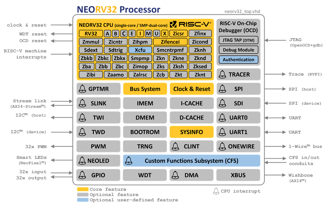 |
|
The NEORV32 Processor is a customizable microcontroller-like system on chip (SoC) that is based on the RISC-V NEORV32 CPU. |
The NEORV32 Processor is a **customizable microcontroller-like system on chip (SoC)** that is based on the RISC-V NEORV32 CPU. |
The project is intended as auxiliary processor in larger SoC designs or as *ready-to-go* stand-alone |
custom / customizable microcontroller. |
custom microcontroller that even fits into a Lattice iCE40 UltraPlus 5k low-power FPGA running at 24 MHz. |
|
Special focus is paid on **execution safety** to provide defined and predictable behavior at any time. |
Therefore, the CPU ensures that all memory access are acknowledged and no invalid/malformed instructions |
are executed. Whenever an unexpected situation occurs, the application code is informed via hardware exceptions. |
are executed. Whenever an unexpected situation occurs the application code is informed via precise and resumable hardware exceptions. |
|
:thinking: Want to know more? Check out the [project's rationale](https://stnolting.github.io/neorv32/#_rationale). |
|
:books: For detailed information take a look at the [NEORV32 documentation (online at GitHub-pages)](https://stnolting.github.io/neorv32/). |
The *doxygen*-based documentation of the *software framework* is also available online |
at [GitHub-pages](https://stnolting.github.io/neorv32/sw/files.html). |
:books: For detailed information take a look at the [NEORV32 documentation](https://stnolting.github.io/neorv32/) (online at GitHub-pages). |
|
:label: The project's change log is available in [`CHANGELOG.md`](https://github.com/stnolting/neorv32/blob/master/CHANGELOG.md). |
To see the changes between *official* releases visit the project's [release page](https://github.com/stnolting/neorv32/releases). |
To see the changes between _official releases_ visit the project's [release page](https://github.com/stnolting/neorv32/releases). |
|
:package: The [`setups`](https://github.com/stnolting/neorv32/tree/master/setups) folder provides exemplary setups targeting |
various FPGA boards and toolchains to get you started. Several example programs (including a FreeRTOS port) to be run on your setup |
can be found in [`sw/example`](https://github.com/stnolting/neorv32/tree/master/sw/example). |
:package: [Exemplary setups](https://github.com/stnolting/neorv32/tree/master/setups) targeting |
various FPGA boards and toolchains to get you started. |
|
:kite: Supported by upstream [Zephyr OS](https://docs.zephyrproject.org/latest/boards/riscv/neorv32/doc/index.html). |
:kite: Supported by upstream [Zephyr OS](https://docs.zephyrproject.org/latest/boards/riscv/neorv32/doc/index.html) and FreeRTOS. |
|
:bulb: Feel free to open a [new issue](https://github.com/stnolting/neorv32/issues) or start a |
[new discussion](https://github.com/stnolting/neorv32/discussions) if you have questions, comments, ideas or if something is |
not working as expected. Or have a chat on our [gitter channel](https://gitter.im/neorv32/community). |
See how to [contribute](https://github.com/stnolting/neorv32/blob/master/CONTRIBUTING.md). |
|
:rocket: Check out the [quick links below](#5-Getting-Started) or directly jump to the |
[*User Guide*](https://stnolting.github.io/neorv32/ug/) to get started |
72,18 → 59,27
|
### Project Key Features |
|
- [x] all-in-one: [CPU](#3-NEORV32-CPU-Features) plus [SoC](#2-NEORV32-Processor-Features) plus [Software Framework & Tooling](#4-Software-Framework-and-Tooling) |
- [x] all-in-one package: [CPU](#3-NEORV32-CPU-Features) plus [SoC](#2-NEORV32-Processor-Features) plus [Software Framework & Tooling](#4-Software-Framework-and-Tooling) |
- [x] completely described in behavioral, platform-independent VHDL - no primitives, macros, etc. |
- [x] fully synchronous design, no latches, no gated clocks |
- [x] be as small as possible while being as RISC-V-compliant as possible – but with a reasonable size-performance trade-off: |
the processor (CPU _including_ privileged architecture) fits into a Lattice iCE40 UltraPlus 5k low-power FPGA running at 24 MHz |
- [x] from zero to `printf("hello world!");` - completely open source and documented |
- [x] be as small as possible while being as RISC-V-compliant as possible |
- [x] from zero to *printf("hello world!");* - completely open source and documented |
- [x] easy to use even for FPGA/RISC-V starters – intended to work *out of the box* |
|
|
### Status |
|
[](https://github.com/stnolting/neorv32/releases) |
[](https://stnolting.github.io/neorv32) |
[](https://github.com/stnolting/neorv32/actions?query=workflow%3ADocumentation) |
\ |
[](https://github.com/stnolting/neorv32/actions?query=workflow%3Ariscv-arch-test) |
[](https://github.com/stnolting/neorv32/actions?query=workflow%3AProcessor) |
[](https://github.com/stnolting/neorv32/actions?query=workflow%3AImplementation) |
[](https://github.com/stnolting/neorv32/actions?query=workflow%3AWindows) |
|
[[back to top](#The-NEORV32-RISC-V-Processor)] |
|
|
|
## 2. NEORV32 Processor Features |
|
The NEORV32 Processor (top entity: [`rtl/core/neorv32_top.vhd`](https://github.com/stnolting/neorv32/blob/master/rtl/core/neorv32_top.vhd)) |
104,7 → 100,7
* general purpose 32-bit timer ([GPTMR](https://stnolting.github.io/neorv32/#_general_purpose_timer_gptmr)) |
* watchdog timer ([WDT](https://stnolting.github.io/neorv32/#_watchdog_timer_wdt)) |
|
**IO** |
**Input/Output** |
|
* standard serial interfaces |
([UART](https://stnolting.github.io/neorv32/#_primary_universal_asynchronous_receiver_and_transmitter_uart0), |
114,7 → 110,7
[PWM](https://stnolting.github.io/neorv32/#_pulse_width_modulation_controller_pwm) |
* smart LED interface ([NEOLED](https://stnolting.github.io/neorv32/#_smart_led_interface_neoled)) to directly drive _NeoPixel(TM)_ LEDs |
|
**SoC Connectivity and Integration** |
**SoC Connectivity** |
|
* 32-bit external bus interface, Wishbone b4 compatible |
([WISHBONE](https://stnolting.github.io/neorv32/#_processor_external_memory_interface_wishbone_axi4_lite)) |
147,9 → 143,10
of the online datasheet shows the resource utilization of each optional processor module to allow an |
estimation of the actual setup's hardware requirements. |
|
:information_source: The [`setups`](https://github.com/stnolting/neorv32/tree/master/setups) folder provides exemplary FPGA |
The [`setups`](https://github.com/stnolting/neorv32/tree/master/setups) folder provides exemplary FPGA |
setups targeting various FPGA boards and toolchains. These setups also provide resource utilization reports for different |
SoC configurations |
SoC configurations. The latest utilization reports for those setups can be found in the report of the |
[Implementation Workflow](https://github.com/stnolting/neorv32/actions/workflows/Implementation.yml). |
|
[[back to top](#The-NEORV32-RISC-V-Processor)] |
|
199,7 → 196,7
[[`DEBUG`](https://stnolting.github.io/neorv32/#_cpu_debug_mode)]** |
|
:warning: The `B`, `Zfinx` and `Zmmul` RISC-V extensions are frozen but not officially ratified yet. Hence, there is no |
upstream gcc support. To circumvent this, the NEORV32 software framework provides _intrinsic_ libraries for these extensions. |
upstream gcc support. To circumvent this, the NEORV32 software framework provides _intrinsic libraries_ for these extensions. |
|
[[back to top](#The-NEORV32-RISC-V-Processor)] |
|
207,21 → 204,18
### FPGA Implementation Results - CPU |
|
Implementation results for _exemplary_ CPU configuration generated for an **Intel Cyclone IV EP4CE22F17C6N FPGA** |
using **Intel Quartus Prime Lite 20.1** ("balanced implementation"). The timing information is derived |
from the Timing Analyzer / Slow 1200mV 0C Model. No constraints were used at all. |
using **Intel Quartus Prime Lite 20.1** ("balanced implementation, Slow 1200mV 0C Model"). |
|
Results generated for hardware version [`1.5.7.10`](https://github.com/stnolting/neorv32/blob/master/CHANGELOG.md). |
| CPU Configuration (version [1.5.7.10](https://github.com/stnolting/neorv32/blob/master/CHANGELOG.md)) | LEs | FFs | Memory bits | DSPs (9-bit) | f_max | |
|:------------------------|:----:|:----:|:----:|:-:|:-------:| |
| `rv32i` | 806 | 359 | 1024 | 0 | 125 MHz | |
| `rv32i_Zicsr_Zicntr` | 1729 | 813 | 1024 | 0 | 124 MHz | |
| `rv32imac_Zicsr_Zicntr` | 2511 | 1074 | 1024 | 0 | 124 MHz | |
|
| CPU Configuration | LEs | FFs | Memory bits | DSPs (9-bit) | f_max | |
|:--------------------------------------------------|:----:|:----:|:-----------:|:------------:|:-------:| |
| `rv32i` | 806 | 359 | 1024 | 0 | 125 MHz | |
| `rv32i_Zicsr_Zicntr` | 1729 | 813 | 1024 | 0 | 124 MHz | |
| `rv32imac_Zicsr_Zicntr` | 2511 | 1074 | 1024 | 0 | 124 MHz | |
|
:information_source: An incremental list of CPU extension's hardware utilization can found in the |
[_Data Sheet: FPGA Implementation Results - CPU_](https://stnolting.github.io/neorv32/#_cpu). |
|
:information_source: The CPU (and also the SoC) provides advanced options to optimize for performance, area or energy. |
:information_source: The CPU and SoC provide advanced options to optimize for performance, area or energy. |
See [_User Guide: Application-Specific Processor Configuration_](https://stnolting.github.io/neorv32/ug/#_application_specific_processor_configuration) |
for more information. |
|
230,25 → 224,19
|
### Performance |
|
The NEORV32 CPU is based on a two-stages pipelined architecture. Since both stage use a multi-cycle processing scheme, |
each instruction requires several clock cycles to execute (2 cycles for ALU operations, up to 40 cycles for divisions). |
The NEORV32 CPU is based on a two-stages pipeline architecture (fetch and execute). |
The average CPI (cycles per instruction) depends on the instruction mix of a specific applications and also on the |
available CPU extensions. |
|
The following table shows the performance results (relative CoreMark score and average cycles per instruction) for |
_exemplary_ CPU configuration running 2000 iterations of the CoreMark CPU benchmark. |
The source files are available in [`sw/example/coremark`](https://github.com/stnolting/neorv32/blob/master/sw/example/coremark). |
A simple(!) port of the **Dhrystone** benchmark is also available in |
[`sw/example/dhrystone`](https://github.com/stnolting/neorv32/blob/master/sw/example/dhrystone). |
The following table shows the performance results (scores and average CPI) for _exemplary_ CPU configurations executing |
2000 iterations of the [CoreMark](https://github.com/stnolting/neorv32/blob/master/sw/example/coremark) CPU benchmark. |
|
Results generated for hardware version [`1.5.7.10`](https://github.com/stnolting/neorv32/blob/master/CHANGELOG.md). |
| CPU Configuration (version [1.5.7.10](https://github.com/stnolting/neorv32/blob/master/CHANGELOG.md)) | CoreMark Score | CoreMarks/MHz | Average CPI | |
|:------------------------------------------------|:-----:|:----------:|:--------:| |
| _small_ (`rv32i_Zicsr`) | 33.89 | **0.3389** | **4.04** | |
| _medium_ (`rv32imc_Zicsr`) | 62.50 | **0.6250** | **5.34** | |
| _performance_ (`rv32imc_Zicsr` + perf. options) | 95.23 | **0.9523** | **3.54** | |
|
| CPU Configuration | CoreMark Score | CoreMarks/MHz | Average CPI | |
|:------------------------------------------------|:--------------:|:-------------:|:-----------:| |
| _small_ (`rv32i_Zicsr`) | 33.89 | **0.3389** | **4.04** | |
| _medium_ (`rv32imc_Zicsr`) | 62.50 | **0.6250** | **5.34** | |
| _performance_ (`rv32imc_Zicsr` + perf. options) | 95.23 | **0.9523** | **3.54** | |
|
:information_source: More information regarding the CPU performance can be found in the |
[_Data Sheet: CPU Performance_](https://stnolting.github.io/neorv32/#_cpu_performance). |
|
258,24 → 246,24
|
## 4. Software Framework and Tooling |
|
:books: In-depth detailed information regarding the software framework can be found in the |
[_Data Sheet: Software Framework_](https://stnolting.github.io/neorv32/#_software_framework). |
|
* [core libraries](https://github.com/stnolting/neorv32/tree/master/sw/lib) for high-level usage of the provided functions and peripherals |
* application compilation based on GNU makefiles |
* gcc-based toolchain ([pre-compiled toolchains available](https://github.com/stnolting/riscv-gcc-prebuilt)) |
* [SVD file](https://github.com/stnolting/neorv32/tree/master/sw/svd) for advanced debugging and IDE integration |
* bootloader with UART interface console |
* runtime environment for handling traps |
* several [example programs](https://github.com/stnolting/neorv32/tree/master/sw/example) to get started including CoreMark, FreeRTOS and Conway's Game of Life |
* `doxygen`-based documentation, available on :books: [GitHub pages](https://stnolting.github.io/neorv32/sw/files.html) |
* supports implementation using open source tooling (GHDL, Yosys and nextpnr; in the future Verilog-to-Routing); both, software and hardware can be |
* doxygen-based documentation, available on [GitHub pages](https://stnolting.github.io/neorv32/sw/files.html) |
* supports implementation using open source tooling (GHDL, Yosys and nextpnr; in the future: "Verilog-to-Routing") - both, software and hardware can be |
developed and debugged with open source tooling |
* [continuous integration](https://github.com/stnolting/neorv32/actions) :octocat: is available for: |
* [continuous integration](https://github.com/stnolting/neorv32/actions) is available for: |
* allowing users to see the expected execution/output of the tools |
* ensuring specification compliance |
* catching regressions |
* providing ready-to-use and up-to-date bitstreams and documentation |
|
:books: Want to know more? Check out [_Data Sheet: Software Framework_](https://stnolting.github.io/neorv32/#_software_framework). |
|
[[back to top](#The-NEORV32-RISC-V-Processor)] |
|
|
294,7 → 282,7
* [Top Entity - Signals](https://stnolting.github.io/neorv32/#_processor_top_entity_signals) - how to connect to the processor |
* [Top Entity - Generics](https://stnolting.github.io/neorv32/#_processor_top_entity_generics) - configuration options |
* [Address Space](https://stnolting.github.io/neorv32/#_address_space) - memory layout and boot configuration |
* [SoC Modules](https://stnolting.github.io/neorv32/#_processor_internal_modules) - available IO/peripheral modules and memories |
* [SoC Modules](https://stnolting.github.io/neorv32/#_processor_internal_modules) - available peripheral modules and memories |
* [On-Chip Debugger](https://stnolting.github.io/neorv32/#_on_chip_debugger_ocd) - online & in-system debugging of the processor via JTAG |
|
* [NEORV32 CPU](https://stnolting.github.io/neorv32/#_neorv32_central_processing_unit_cpu) - the CPU |
306,6 → 294,7
|
### :floppy_disk: Software Overview |
|
* [Example Programs](https://github.com/stnolting/neorv32/tree/master/sw/example) - test program execution on your setup |
* [Core Libraries](https://stnolting.github.io/neorv32/#_core_libraries) - high-level functions for accessing the processor's peripherals |
* [Software Framework Documentation](https://stnolting.github.io/neorv32/sw/files.html) - `doxygen`-based documentation |
* [Application Makefiles](https://stnolting.github.io/neorv32/#_application_makefile) - turning your application into an executable |
313,7 → 302,7
|
### :rocket: User Guide |
|
* [Toolchain Setup](https://stnolting.github.io/neorv32/ug/#_toolchain_setup) - install and setup RISC-V gcc |
* [Toolchain Setup](https://stnolting.github.io/neorv32/ug/#_software_toolchain_setup) - install and setup RISC-V gcc |
* [General Hardware Setup](https://stnolting.github.io/neorv32/ug/#_general_hardware_setup) - setup a new NEORV32 EDA project |
* [General Software Setup](https://stnolting.github.io/neorv32/ug/#_general_software_framework_setup) - configure the software framework |
* [Application Compilation](https://stnolting.github.io/neorv32/ug/#_application_program_compilation) - compile an application using `make` |
326,10 → 315,13
|
### :copyright: Legal |
|
* [Overview](https://stnolting.github.io/neorv32/#_legal) - license, disclaimer, proprietary notice, ... |
* [Citing](https://stnolting.github.io/neorv32/#_citing) - citing information (DOI) |
* [Impressum](https://github.com/stnolting/neorv32/blob/master/docs/impressum.md) - imprint (:de:) |
[](https://github.com/stnolting/neorv32/blob/master/LICENSE) |
[](https://doi.org/10.5281/zenodo.5018888) |
|
* [Overview](https://stnolting.github.io/neorv32/#_legal) - license, disclaimer, limitation of liability for external links, proprietary notice, ... |
* [Citing](https://stnolting.github.io/neorv32/#_citing) - citing information |
* [Impressum](https://github.com/stnolting/neorv32/blob/master/docs/impressum.md) - imprint |
|
[[back to top](#The-NEORV32-RISC-V-Processor)] |
|
|
336,7 → 328,7
|
## Acknowledgements |
|
**A big shout-out to the community and all [contributors](https://github.com/stnolting/neorv32/graphs/contributors), who helped improving this project! :heart:** |
**A big shout-out goes to the community and all the [contributors](https://github.com/stnolting/neorv32/graphs/contributors), who helped improving this project! :heart:** |
|
[RISC-V](https://riscv.org/) - Instruction Sets Want To Be Free! |
|