Serializer / Deserializer for audio fiber optic
Project maintainers
Details
Created: Dec 12, 2013
Updated: Apr 28, 2014
SVN Updated: Dec 14, 2013
SVN: Browse
Latest version: download (might take a bit to start...)
Statistics: View
Bugs: 0 reported / 0 solved
Other project properties
Language:VHDL
Development status:Mature
Additional info:Design done, FPGA proven, Specification done
WishBone compliant: No
WishBone version: n/a
License: LGPL
Description
A device that convert a PC parallel port to serial , then serial to parallel. It can transport all signals of the PC parallel port into a single wire. Moreover, the data wire is intended to be a fiber optic in the final form of the project.
Overview
Project idea :
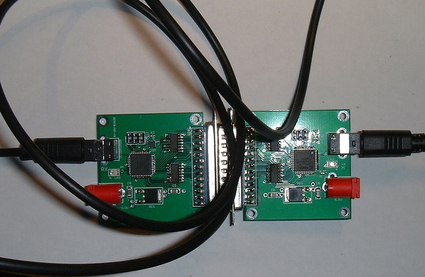
I would like to show you how I control my CNC equipment (which is usually controlled by a PC parallel port) with a single wire using a special FPGA device.
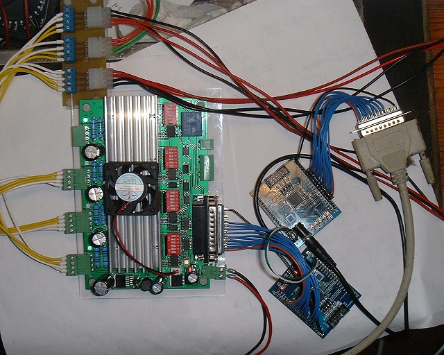
The FPGA device serialize the control signals from the parallel port , transport the data through a single wire , then deserialize the data at arrival.
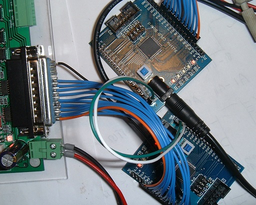
This is the close view of the data wire (white color). The other wire (Green) is reference 0V.
SUBD 25 socket
Parallel port SUBD-25 pin with controls (s0-s11) , input (i0,i4)
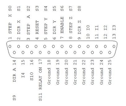
The 25 pin SUBD-25 socket is as follow :
12 control signals S0-S11
5 input signals I0-I4
The function of the control signals are either :
digital signals (RESET,ENABLE, RELAY)
stepper motor signals (STEP and DIR) of each of 4 axis X,Y,Z,A
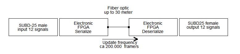
Frame data format
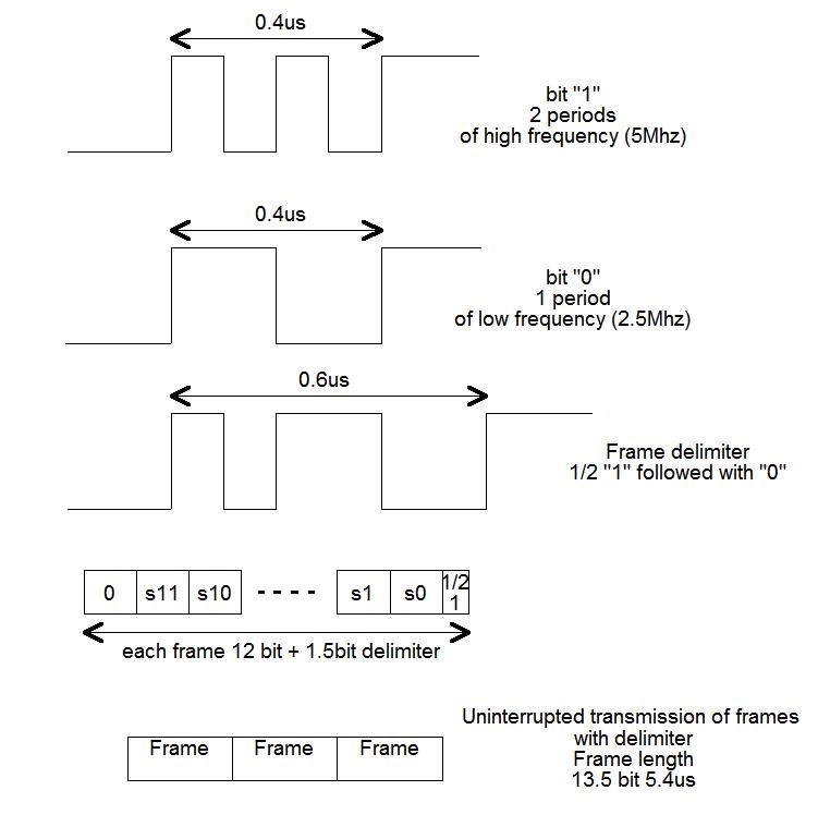
The frame delimiter is 1.5 bit duration and is the overhead that add to payload of each frame. The receiver can easily detect the frame delimiter pattern as well as each bit "0" or "1" of the frame.
200.000 frames approx. are transmitted each second and this update frequency is ok for normal digital signals like clear, enable , relay control. It is ok also for variable signals in the range 1000-3000Hz like PWM speed control.
But it is not enough for stepper motor control signals (STEP and DIR) . I will talk more about that in the next paragraph.
STEP and DIR
Lets explain how a CNC stepper motor controller works
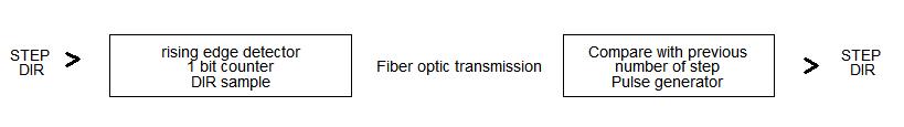
The controller count rising edges of the STEP signal. At each step edge, the controller sample the DIR signal and advance motor in the direction of DIR.
The STEP and DIR signals cannot be transmitted on the serial link like normal control signals , because they are registered pulse signals.
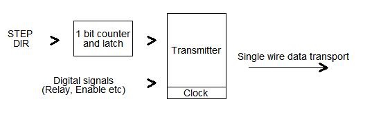
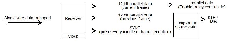
The serializer , in that case incorporate a 1-bit step counter and a dir latch . The Serializer transmit the number of step (modulo 2) + the DIR value on the most recent step edge.
The deserializer will compare the number of step of each frame with the previous frame and allow/disallow a pulse on the corresponding output.
Fortunately the serializer OR deserializer fit into a single XC9572XL CPLD . With 4 STEP+DIR signal pair.
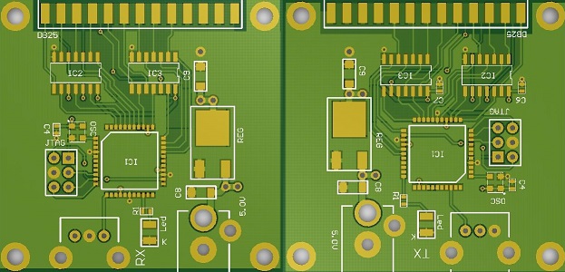
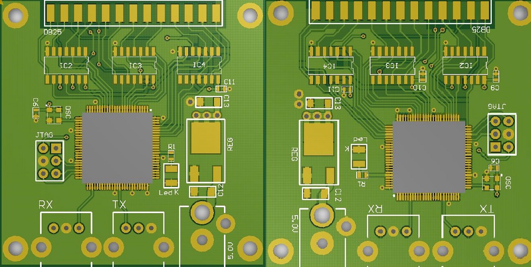
Transmitter
Receiver
Bill of material
XC9572XL Xilinx CPLD (1 for transmitter + 1 for receiver)
50Mhz 3.3V CMOS oscillator
PLR/PLT133-T7 Everlight electronic fiber optic modules
Audio (SPDIF) fiber optic cable
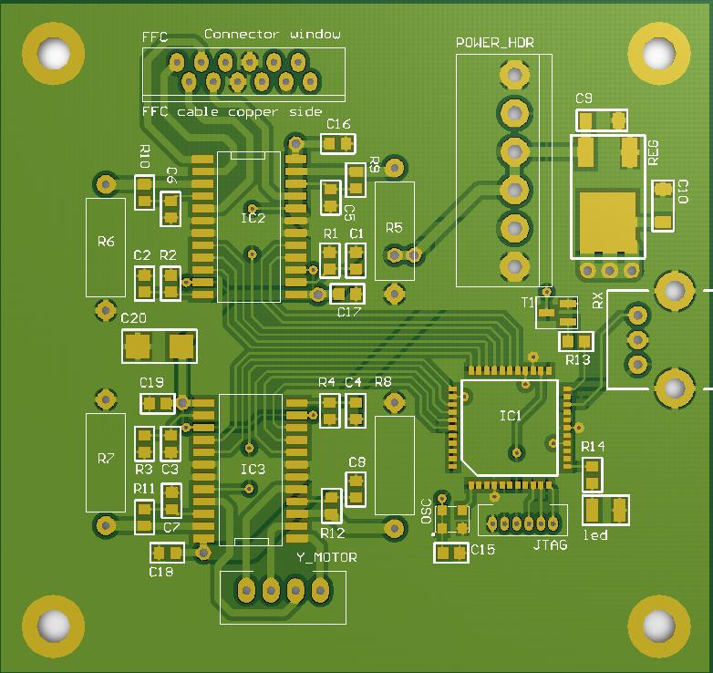
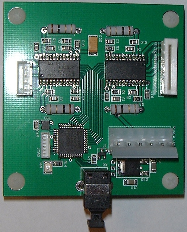
Perspective
serial to parallel and Parallel to serial fiber optic PCB module including 5V to 3.3V IO buffer.
Dec 27 2013 ===>> Finished product (Work as expected)
Bidirectionnal interface
Boards with XC95144XL CPLD , implementing bidirectionnal link
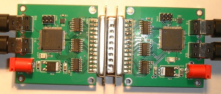
Finished jan/24/2014 work as expected
Application
An application : A replacement card for a laser engraver (model K40) , with stepper motor driver.
The single fiber optic input, provide a complete electric insulation between the PC and the laser engraver.
Application 2
Stepper motor PWM controller with single fiber optic input.
Assembled (jan 6 2014)
Working video : http://youtu.be/0FW8_HkqzNM
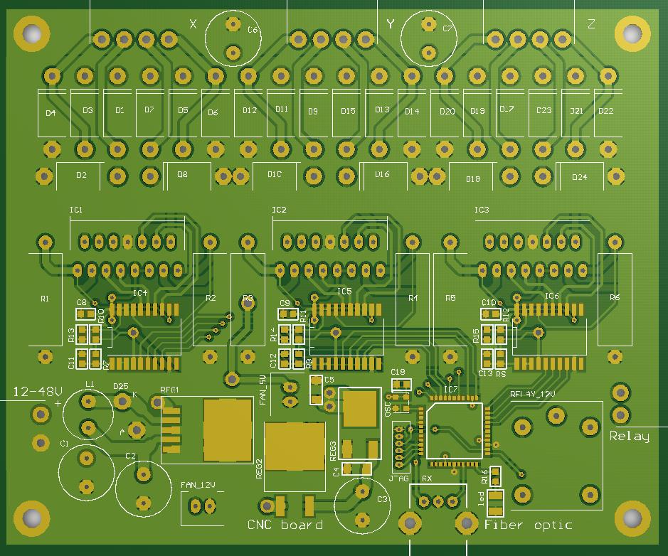
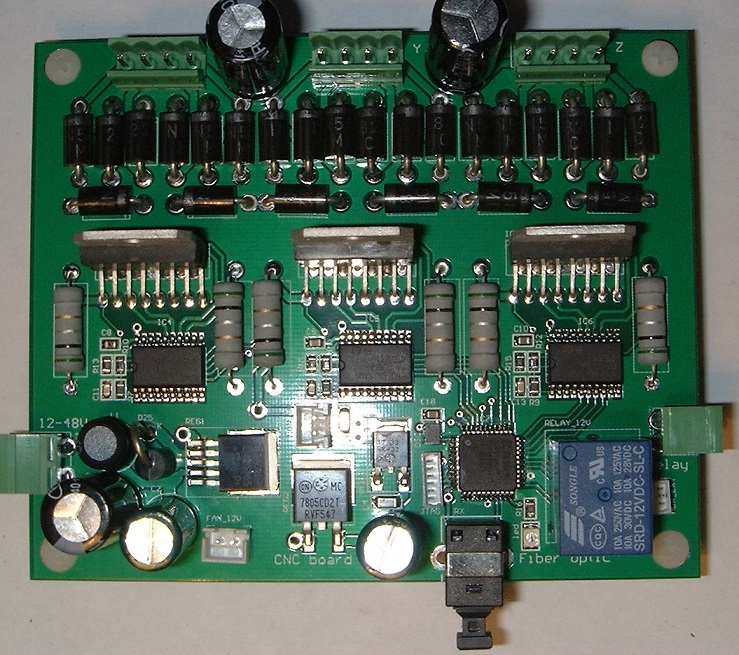
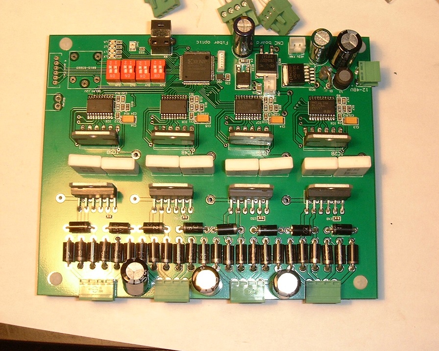
Application 3
High current PWM stepper board (4A /coil) with 6 DMOS full bridge ( 2 per motor) + fiber optic interface and 4th axis extension
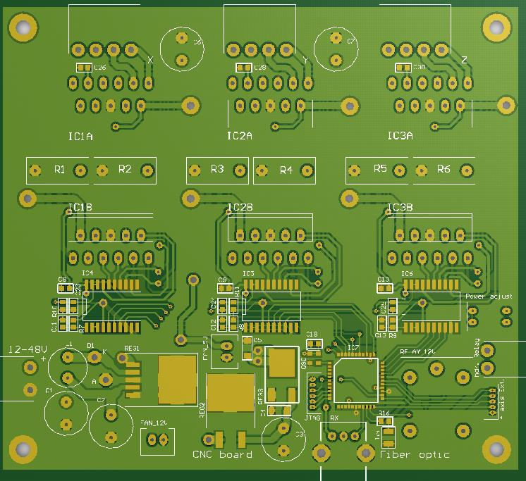
Finished - Transformed to 4 axis - added discharge diodes - Changed XC9572 to XC95144 - Added separate power setting for each axis
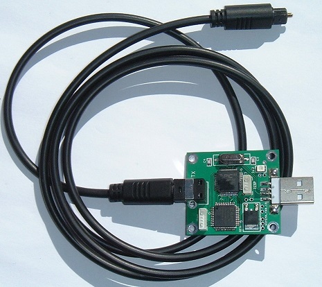
USB interface for CNC on fiber optic