
Pmod DA4 Driver
Project maintainers
Details
Created: Feb 6, 2025
Updated: Feb 10, 2025
SVN Updated: Feb 10, 2025
SVN: Browse
Latest version: download (might take a bit to start...)
Statistics: View
Bugs: 0 reported / 0 solved
Other project properties
Language:VHDL
Development status:Beta
Additional info:
WishBone compliant: No
WishBone version: n/a
License: LGPL
PmodDA4Driver
Pmod DA4 Driver for the 8 Channels 12-bit Digital-to-Analog Converter AD5628. This module implements a Pmod DA4 Driver for the 8 Channels 12-bit Digital-to-Analog Converter AD5628. The communication with the DAC uses the SPI protocol (Write only). User can specifies the SPI Serial Clock Frequency (up to 50 MHz).
Usage
The o_ready signal (set to '1') indicates the PmodDA4Driver is ready to receive new data (command, address and digital value). Once data are set, the i_enable signal can be triggered (set to '1') to begin transmission. The o_ready signal is set to '0' to acknowledge the receipt and the application of the new data. When the transmission is complete, the o_ready is set to '1' and the PmodDA4Driver is ready for new transmission.
Commands:
| C3 | C2 | C1 | C0 | Description |
|---|---|---|---|---|
| 0 | 0 | 0 | 0 | Write to Input Register n |
| 0 | 0 | 0 | 1 | Update DAC Register n |
| 0 | 0 | 1 | 0 | Write to Input Register n, update all (software /LDAC) |
| 0 | 0 | 1 | 1 | Write to and update DAC Channel n |
| 0 | 1 | 0 | 0 | Power down/power up DAC |
| 0 | 1 | 0 | 1 | Load clear code register |
| 0 | 1 | 1 | 0 | Load /LDAC register |
| 0 | 1 | 1 | 1 | Reset (power-on reset) |
| 1 | 0 | 0 | 0 | Set up internal REF register |
| - | - | - | - | Reserved |
Address:
| A3 | A2 | A1 | A0 | Description |
|---|---|---|---|---|
| 0 | 0 | 0 | 0 | DAC Channel A |
| 0 | 0 | 0 | 1 | DAC Channel B |
| 0 | 0 | 1 | 0 | DAC Channel C |
| 0 | 0 | 1 | 1 | DAC Channel D |
| 0 | 1 | 0 | 0 | DAC Channel E |
| 0 | 1 | 0 | 1 | DAC Channel F |
| 0 | 1 | 1 | 0 | DAC Channel G |
| 0 | 1 | 1 | 1 | DAC Channel H |
| 1 | 1 | 1 | 1 | DAC All Channels |
Signal Generator Pin Description
Generics
| Name | Description |
|---|---|
| sys_clock | System Input Clock Frequency (Hz) |
| spi_clock | SPI Serial Clock Frequency (up to 50 MHz) |
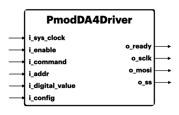
Ports
| Name | Type | Description |
|---|---|---|
| i_sys_clock | Input | System Input Clock |
| i_enable | Input | Module Enable ('0': Disable, '1': Enable) |
| i_command | Input | DAC Command (4 bits) |
| i_addr | Input | DAC Address Register (4 bits) |
| i_digital_value | Input | DAC Value (12 bits) |
| i_config | Input | DAC Configuration Bits (8 bits) |
| o_ready | Output | Ready to convert Next Digital Value ('0': NOT Ready, '1': Ready) |
| o_sclk | Output | SPI Serial Clock |
| o_mosi | Output | SPI Master Output Slave Input Data line |
| o_ss | Output | SPI Slave Select Line ('0': Enable, '1': Disable) |