SPIMaster
Project maintainers
Details
Name: spi_master
Created: Nov 13, 2024
Updated: Nov 14, 2024
SVN Updated: Nov 14, 2024
SVN: Browse
Latest version: download (might take a bit to start...)
Statistics: View
Bugs: 0 reported / 0 solved
Created: Nov 13, 2024
Updated: Nov 14, 2024
SVN Updated: Nov 14, 2024
SVN: Browse
Latest version: download (might take a bit to start...)
Statistics: View
Bugs: 0 reported / 0 solved
Star0you like it: star it!
Other project properties
Category:Communication controller
Language:VHDL
Development status:Beta
Additional info:
WishBone compliant: No
WishBone version: n/a
License: LGPL
Language:VHDL
Development status:Beta
Additional info:
WishBone compliant: No
WishBone version: n/a
License: LGPL
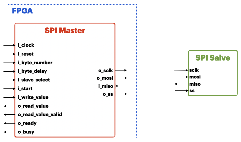
SPI Master
This module implements SPI master protocol, supporting:
- CPOL Configuration
- CPHA Configuration
- Slave Select Polarity (active Low or High)
- 2-Byte Delay Interval (0 to 7 SPI Clock Cycles)
- Byte Number Configuration
- Daisy-Chain (Slaves MUST support this feature)

Usage
The Ready signal indicates no operation is on going and the SPI Master is waiting operation. The Busy signal indicates operation is on going. Reset input can be trigger at any time to reset the SPI Master to the IDLE state.
- Set all necessary inputs
- Byte Number (number of byte required to write/read)
- Byte Delay (number of SPI SCLK Clock Cycles between 2 bytes to write/read)
- Slave Select (set to '1' the Slave Select Line to enable)
- Data to Write
- Asserts Start input. The Ready signal is de-asserted and the Busy signal is asserted.
- SPI Master re-asserts the Ready signal at the end of transmission (Master is ready for a new transmission)
- The read value is available when its validity signal is asserted
SPI Master Pin Description
Generics
| Name | Description |
|---|---|
| input_clock | Module Input Clock Frequency |
| spi_clock | SPI Serial Clock Frequency |
| cpol | SPI Clock Polarity ('0': SCLK IDLE at Low, '1': SCLK IDLE at High) |
| cpha | SPI Clock Phase ('0': Data valid on Leading/First Edge of SCLK, '1': Data valid on Trailing/Second Edge of SCLK) |
| ss_polarity | SPI Slave Select Polarity ('0': active Low, '1': active High) |
| ss_length | Number of Chip/Slave Select Lines |
| max_data_register_length | Maximum SPI Data Register Length in bits |
Ports
| Name | Type | Description |
|---|---|---|
| i_clock | Input | Module Input Clock |
| i_reset | Input | Reset ('0': No Reset, '1': Reset) |
| i_byte_number | Input | SPI Byte Number during the Transmission |
| i_byte_delay | Input | SPI Delay between 2-Byte Transmission (0 to 7 SPI Clock Cycles) |
| i_slave_select | Input | SPI Slave Selection ('0': Not Selected, '1': Selected) |
| i_start | Input | Start SPI Transmission ('0': No Start, '1': Start) |
| i_write_value | Input | Data to Write |
| o_read_value | Output | Data Read from Slave |
| o_read_value_valid | Output | Validity of the Data Read ('0': Not Valid, '1': Valid) |
| o_ready | Output | Ready State of SPI Master ('0': Not Ready, '1': Ready) |
| o_busy | Output | Busy State of SPI Master ('0': Not Busy, '1': Busy) |
| o_sclk | Output | SPI Serial Clock |
| o_mosi | Output | SPI Master Output Slave Input Data line |
| i_miso | Input | SPI Master Input Slave Output Data line |
| o_ss | Output | SPI Slave Select Line (inverted ss_polarity: Not Selected, ss_polarity: Selected) |
© copyright 1999-2018 OpenCores.org, equivalent to Oliscience, all rights reserved. OpenCores®, registered trademark.
