ULA chip for ZX Spectrum
Project maintainers
Details
Created: Apr 23, 2012
Updated: Jan 6, 2013
SVN Updated: Jan 6, 2013
SVN: Browse
Latest version: download (might take a bit to start...)
Statistics: View
Bugs: 0 reported / 0 solved
Other project properties
Language:Verilog
Development status:Beta
Additional info:Design done, FPGA proven, Specification done
WishBone compliant: No
WishBone version: n/a
License: GPL
Description
This is an implementation of the Sinclair ULA chip, found in ZX Spectrum microcomputers. The project offers various implementations: both FPGA friendly (with separate input and output data buses), and CPLD ready, to be used as a replacement for the many chips that comprise the ULA found in some clones.
This project is mostly based upon the work of Chris Smith. Chris designed a ZX Spectrum clon, the "Harlequin". A PCB has been developed by Don "Superfo", which uses discrete logic to implement the ULA, as Chris did. The CPLD version of this implementation is aimed to serve as replacement for that clone.
The ULA implementation follows, where possible, the original ULA timmings, as stated in "The ZX Spectrum ULA: how to design a microcomputer", written by Chris Smith and published by ZX Design and Media, ISBN 978-0-9565071-0-5
There are implementations with some enhancements such as Timex hicolour support and ULA+ support.
Features
- CPLD (XC95144/288XL) version, with shared data bus, designed for the Harlequin clone.
- FPGA (separate input and data buses, mostly synchronous, but I cannot aassure that) version, intented for soft SoC.
- To test the FPGA version, several clones have been built around this ULA core. See directory branches/xilinx. These clones are ready to be used in the Spartan 3 Starter Board, both 200K and 1000K gate versions.
- All timmings according to Chris Smith's specs. Yet to be tested against a real Z80 for timming accuracy (tv80 core seems not to have exact timmings, but this could be my fault, not tv80's)
- Digital IRGB output, PAL timmings. Same signals as found in the 128K heatsink RGB DIN connector, that is, bright component separated from main components.
- 8 bit digital RGB output for ULA+ mode. Output signal indicate whether ULA is in normal or plus mode.
- EAR, MIC and SPK pins
- FPGA version adds the 8-pin row connector for keyboard matrix. See xilinx/ directory for design examples.
- Timex Hicolor mode supported in the FPGA version of the core.
- ULA+ implemented in the FPGA version of the core.
Videos
Testing a ZX Spectrum clone running at 7MHz CPU clock speed. Part I.
Testing a ZX Spectrum clone running at 7MHz CPU clock speed. Part II.
Testing the Timex hicolor mode on a ZX Spectrum ULA enhanced clone.
Testing the Timex hicolor and ULA+ mode with a slideshow.
Images
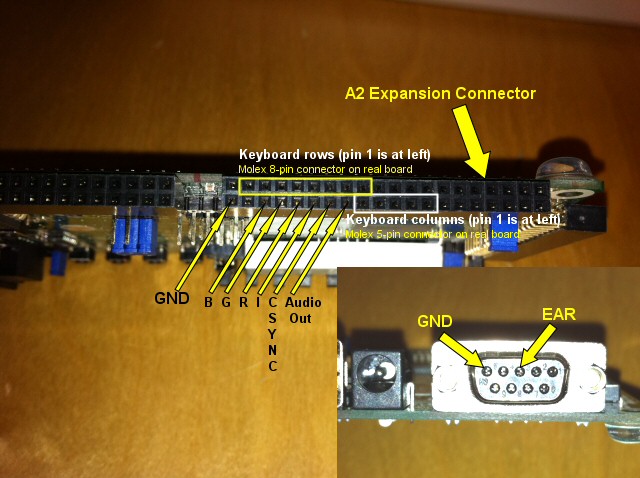
Spartan 3 Starter Board connections for running this clone. RGB signal has separate bright (I) component, so you will need to mix the bright signal before entering the TV/monitor. Usually this is performed by a RGB cable compatible with the 128K heatsink Spectrum, so you will need a female DIN-8 socket and wire it accordingly with your cable (UK or Investronica).
Keyboard connections are not needed with PS2 enabled clones.
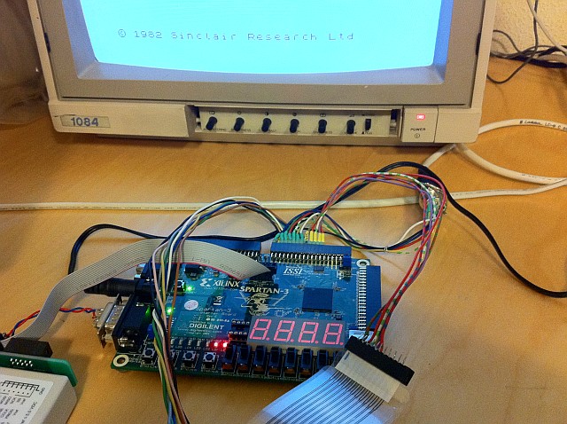
ZX Spectrum design in a Digilent Spartan 3 Starter Board. Real matrix keyboard version.
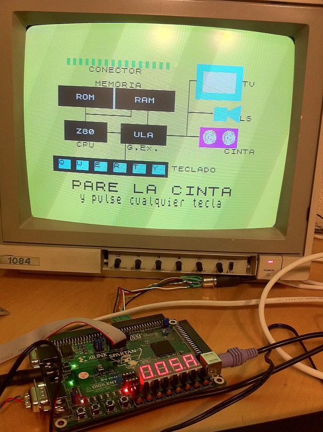
ZX Spectrum clone built around an earler version of the ULA design. This shows the working screen of the first program from the Horizons demo tape (spanish version), the one that teaches the hardware of the Spectrum. Can you name the differences between the elements depicted on screen and the actual hardware that's running them? :D
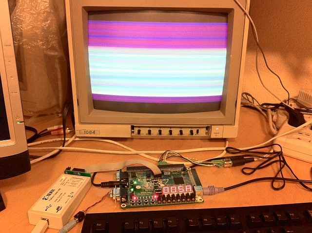
The Overscan demo running in the clone. This is the PS2 enabled keyboard clone version. The PS2 keyboard uses the spanish mapping. English mapping will be ready very soon.
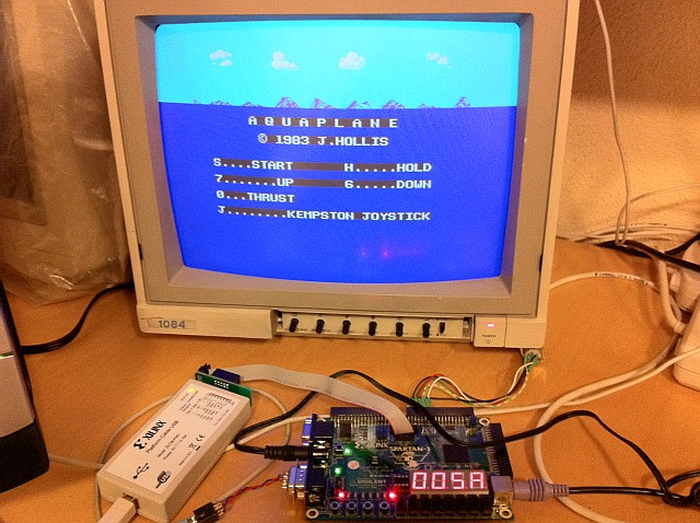
Aquaplane, showing a perfect full screen horizon)
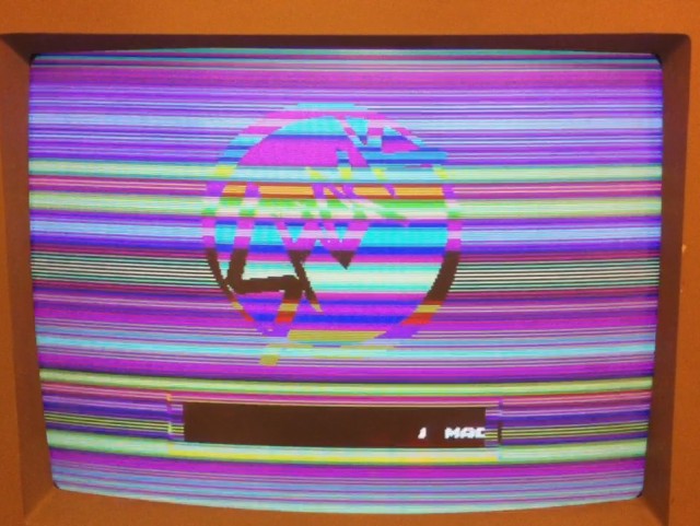
Shock Megademo, part 2. This part is very sensitive to interrupt, ULA and Z80 timmings, so it's a perfect test.
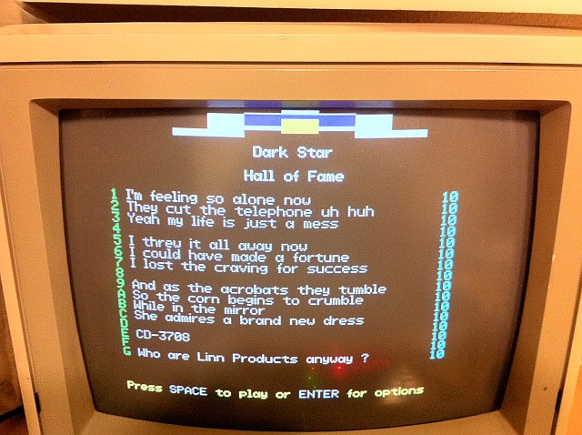
Dark Star. This game features a graphic drawn in the border area. For this to be showed correctly, both interrupt timmings and ULA timmings have to be perfect.
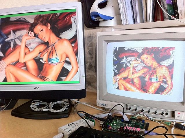
Hicolor Timex demo screen. The "Videos" section features this demo. A new enhanced ULA description which supports this mode has been uploaded to the fpga_version directory. NOTE: only the hicolor mode is supported. The hires mode or the dual screen mode of the Timex TC2048/2068 is not supported.
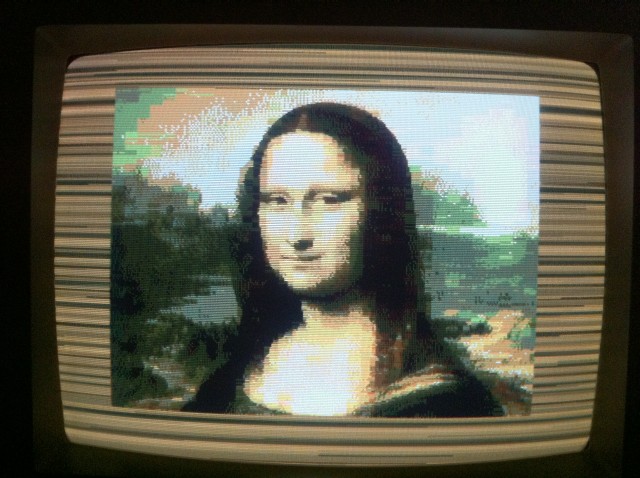
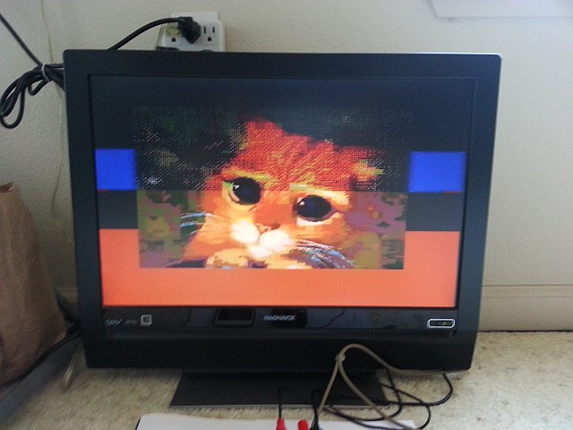
The Gioconda, displayed in the ULA+ & Time HiColor enabled clone. This picture belongs to the new slideshow "Famous pictures" that you can find at the "software/ulaplus_demos" directory in the SVN repository.
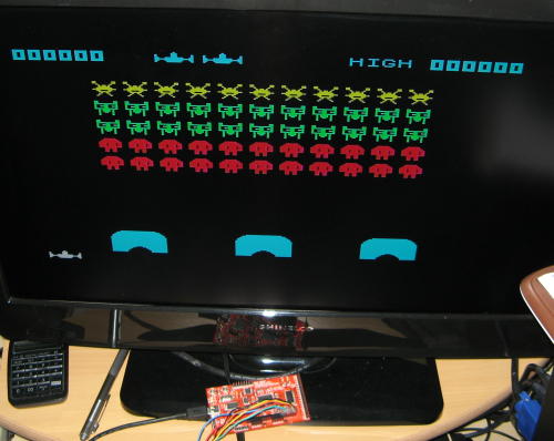
If you want to build one of these clones, but you doesn't have a fancy FPGA trainer board, Joseba Epalza Ramos, from INGEPAL, has sucessfully adapted a Spectrum clone to work entirely within the FPGA in the OLS (no external SRAM required). Of course, this means that this clone cannot have a 16K ROM and at least 16K of RAM, which is the minimum specification for a Spectrum, but there were ROM versions of various games available at the time. Some of these versions were made to fit an 8K ROM chip (cheaper than a 16K ROM). Thus, Joseba's clone features a ROM game (Space Raiders, from Psion Software Ltd) embedded in 8K of block RAM, leaving the rest (16K) to build the first 16K of RAM, including of course, the video RAM.
The clone, showing B/W video: just mix the three RGB signals with weight resistors to get a grayscale signal, which in turn is mixed to the sync signal to get a monocrome video signal you can use to feed the AV INPUT of any TV or video capture device.
The same clone, now using a proper RGB output.
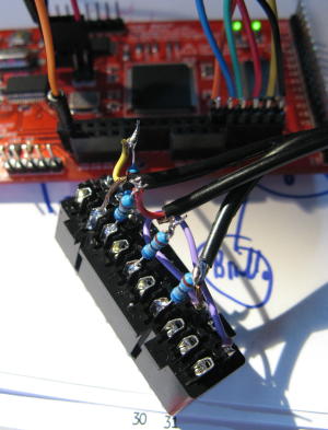
Closeup of the wiring needed to adapt the digital IRGB signals to analog RGB signals. This scheme is the same as shown at the Paul Farrow site
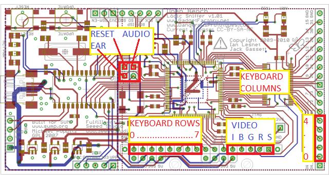
Connection diagram for this clone
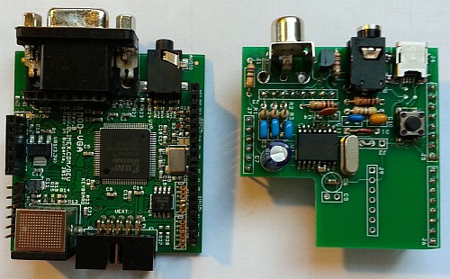
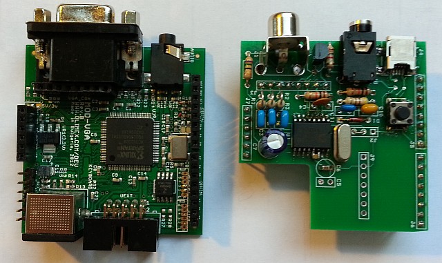
A ZX Spectrum clone built on top of the Gameduino shield by Don "Superfo". Don has added a piggy-back board that connects to the Gameduino.
Bottom view of above design. The Gameduino has footprints to solder either a 512KB SRAM memory, or a 32MB SDRAM. This design uses the SRAM approach.
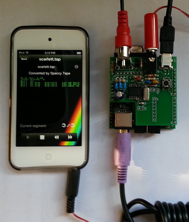
The piggy-back board includes an EAR signal conditioner, so loading from iPhone or MP3 players is not an issue :)
The core is almost the same as used for the ULAplus+Timex Hicolor supported core. Both are available at the project's repository.
A schematic for the piggy-back board is also available.

